

Background:
A vendor developing an aftermarket intake manifold for the Mk7 sent me an early development version to record airflow compared with the stock MK7 intake manifold.

Test Procedure:
An adapter is made to attach the intake manifold to the flow bench. The adapter I made previously for the stock intake manifold will not work with this new intake manifold since the inlet is slightly larger than the stock intake manifold, and the adapter I made before was sized for use with the stock intake manifold.
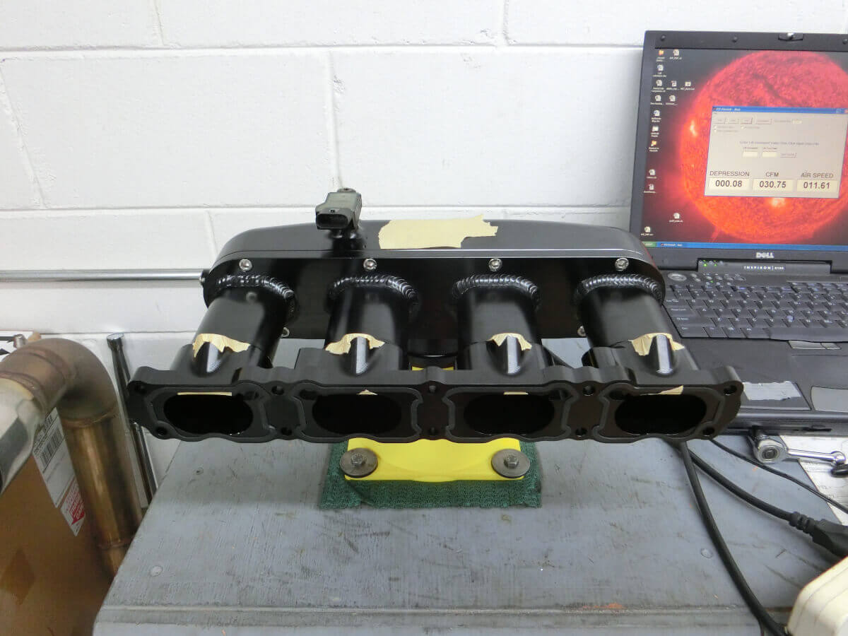
The intake manifold is being tested using the flow bench, all airflow measurements are made at a test depression of 16″ of H2O. The flow bench is configured to exhaust airflow.
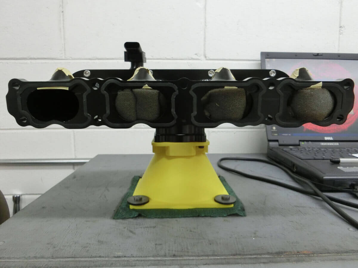
To check individual runners pieces of foam are inserted into the three runners that are not being tested.
Test Results:
Individual runner airflow measurements are shown on the chart along with the stock GTI measurements.

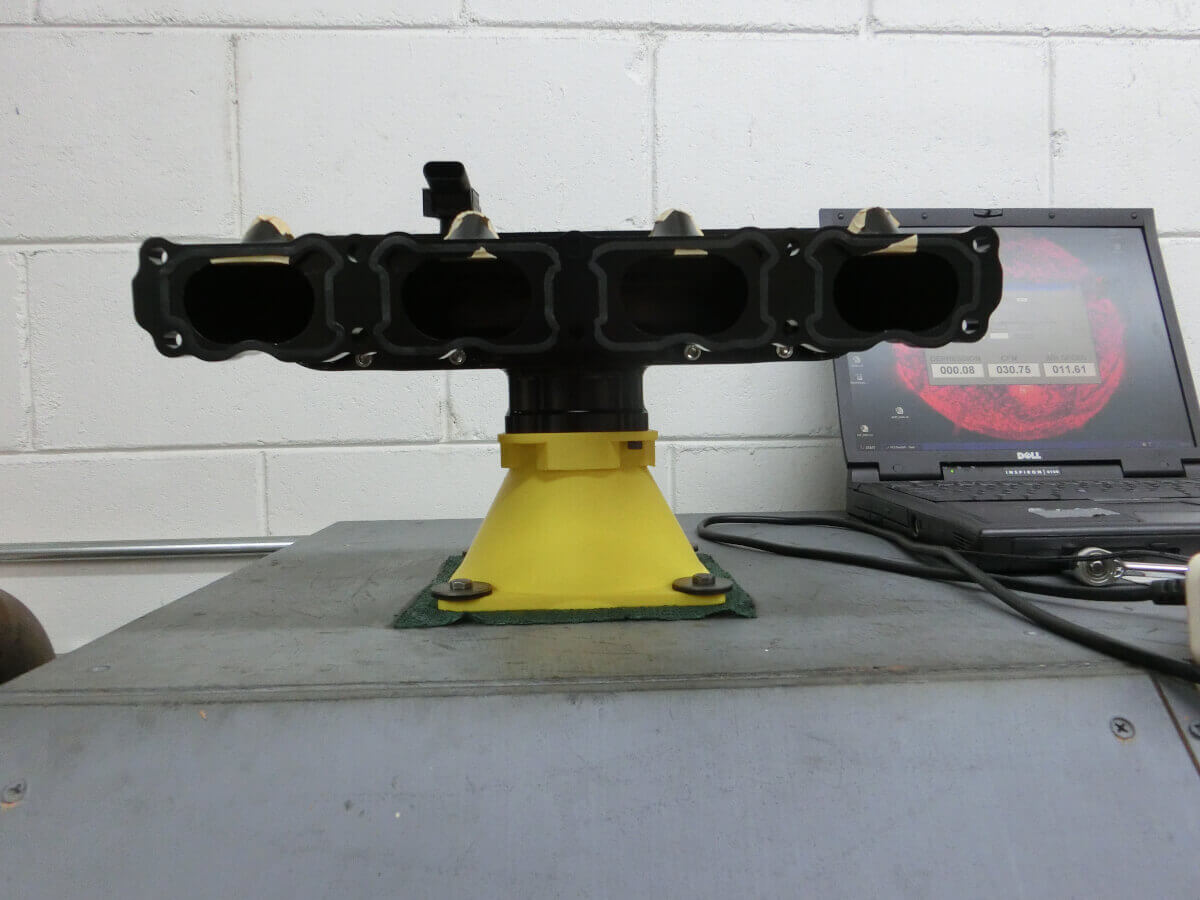
With none of the runners blocked the airflow measured is shown on the next chart:

Conclusions:
An aftermarket intake manifold flow test was conducted and the results were compared with the stock Mk7 GTI intake manifold.
All individual runner measurements of the aftermarket intake manifold showed an increase versus the stock GTI intake manifold.
Increases ranged from 3% to 12%.
With all runners open there was no measurable increase in the airflow through the intake manifold.
Very interesting conclusion and not what I expected to see with all of the runners open. Note that your colors are swapped from the first bar chart to the second.
Hi Jeff
Why did you test with each runner individually? The results don’t make sense, we get better airflow if we test them individually but we get the same airflow if all of them are opened. Could the 458 value be limited by the flow bench?
The individual runner test is to help understand how the airflow is balanced across the runners. I’ve tested other intake manifolds in the past that had more variation across the runners. Also, during the moment when the intake valve opens on one cylinder, the other three will be closed, so air is only entering one cylinder at a time, this tries to replicate that condition.
The bench isn’t a limitation in this case. It’s able to flow over 600 CFM at 28″ of H2O and this was tested at 16″ of H2O, there was a good amount of capacity remaining from the bench.
I’m puzzled by that result.