
Background:
This post looks at how making one change leads to ideas about others, which then leads to trying to make improvements to currently available parts.
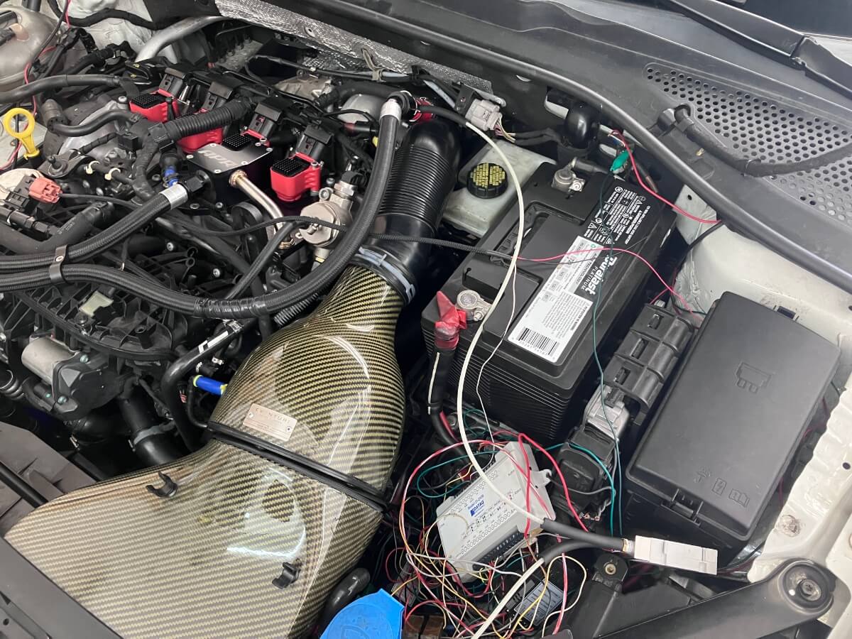
A couple of months ago I changed out the Shuenk IS38+ turbocharger that I have been using for the past several years for a Mabotech M520H, shown below.

For the past few years, my go-to intake has been the Eventuri, primarily due to the smaller size accommodating data logging equipment that I have placed inside the engine compartment.
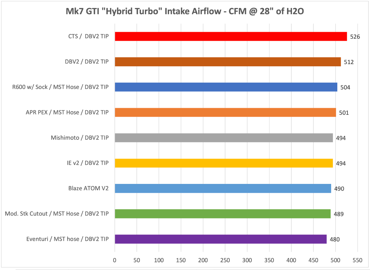
Recently I conducted a flow test with the Eventuri to see how it compared with other intakes that I have tested using a “hybrid” turbocharger adapter. While the Eventuri air filter has been used for several thousand miles, the bottom-of-the-list flow performance still raised concerns about its use with the larger turbocharger.
This led me to consider different intake options for use with the Mabo M520H.
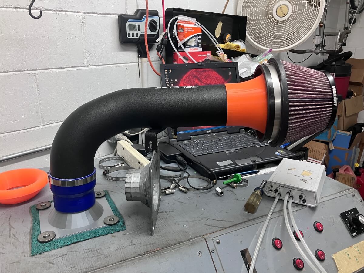
The CTS Turbo intake is a good starting point based on simplicity. A cone air filter stuck on the end of a 3.5″ pipe with a few moderate bends.
I decided to see if I could increase the airflow from this CTS intake.
Baselining:
Before making modifications the intake is tested as supplied by CTS, with one change being the coupler that attaches the intake to the inlet elbow is replaced with a Mishimoto 3.5″ to 3″ coupler. The CTS coupler is sized to fit the stock inlet elbow with a 2.75″ (70 mm) outside diameter.
The intake is then attached to the flow bench using a 3″ adapter. No inlet elbow is being used because this part has been found to limit the airflow through intakes, which is sensible since the outlet of most inlet elbows is around 50-56 mm, much smaller than the 89 mm at the CTS intake pipe outlet.
With no modifications, the CTS intake flows 556 CFM @ 13″ of H2O.
Modifications:
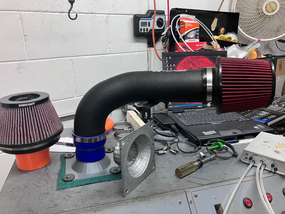
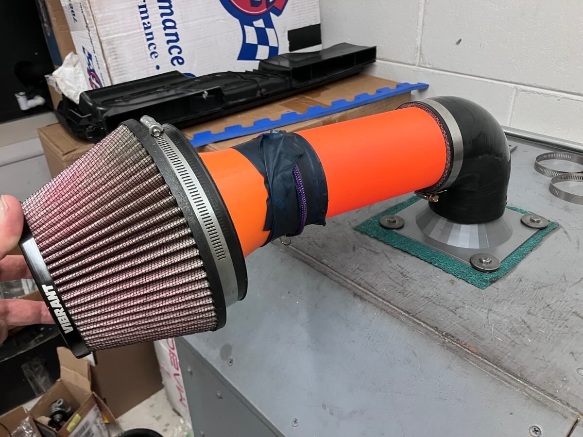
My first idea for changing the intake involves the use of a larger air filter and a couple of different adapter designs for attaching the air filter to the 3.5″ CTS inlet pipe.
The Vibrant 10960 air filter has a 6″ flange opening which provides the space needed to attach it to the inlet pipe using a couple of different velocity stack designs.
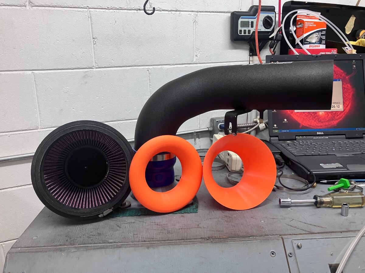
Up first is a tapering shape that extends out to the edge of the air filter flange.
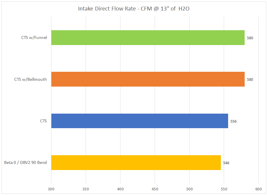
The CTS intake with this “funnel” shaped adapter flows 580 CFM @ 13″ of H2O.
The next test is made using a bellmouth of dimensions that are based on basic data for recommended (NACA) length, exit diameter, entry diameter, and entry corner radius.
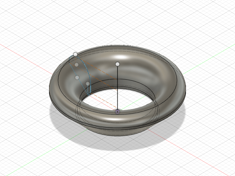
This intake configuration also flows 580 CFM @ 13″ of H2O.

A final flow test is made using a straight 3.5″ tube attached to a 90-degree silicone elbow.
This configuration flows 546 CFM @ 13″ of H2O.
The results for all configurations are shown on the following chart:
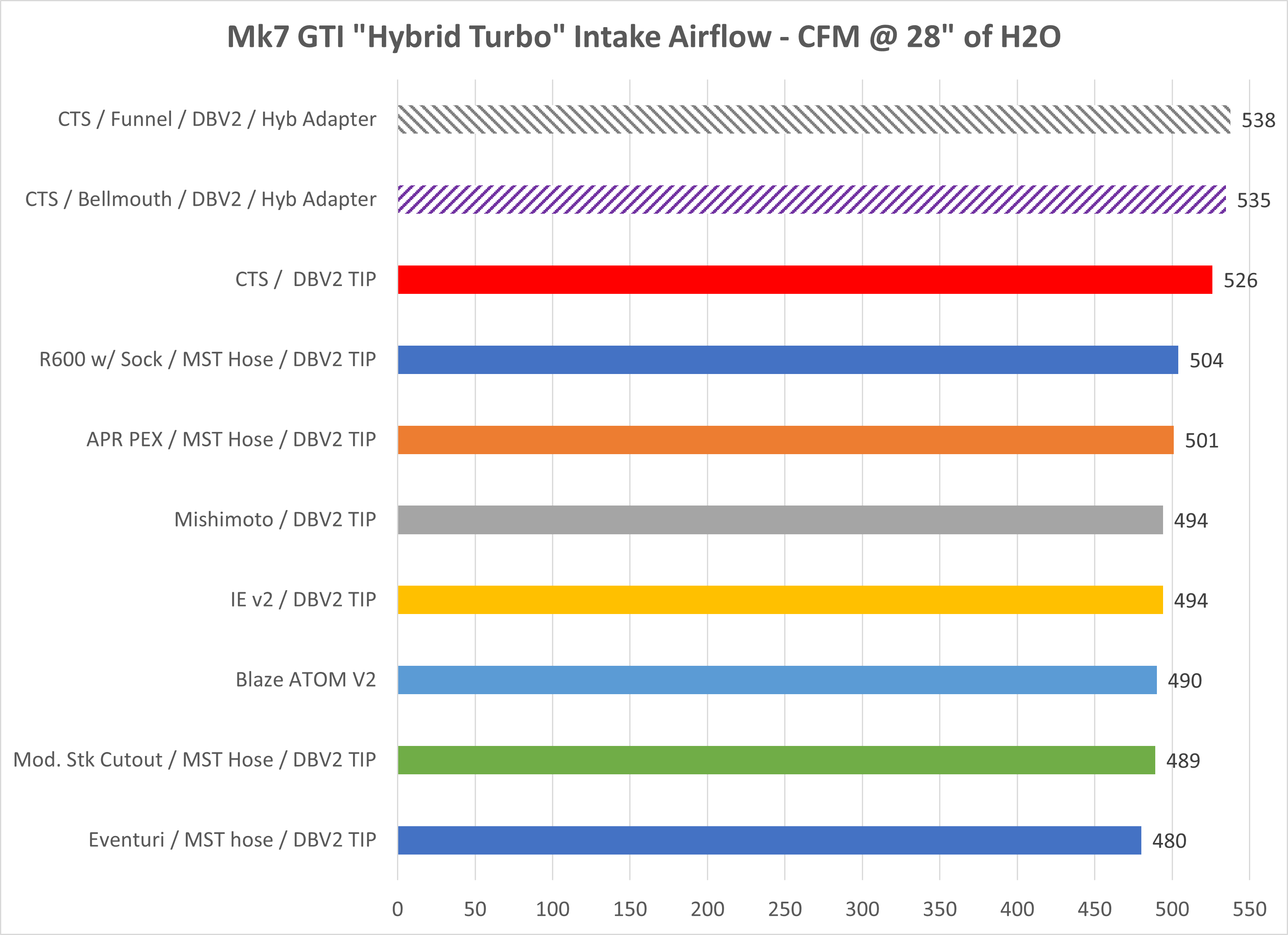
Baseline with TIP:
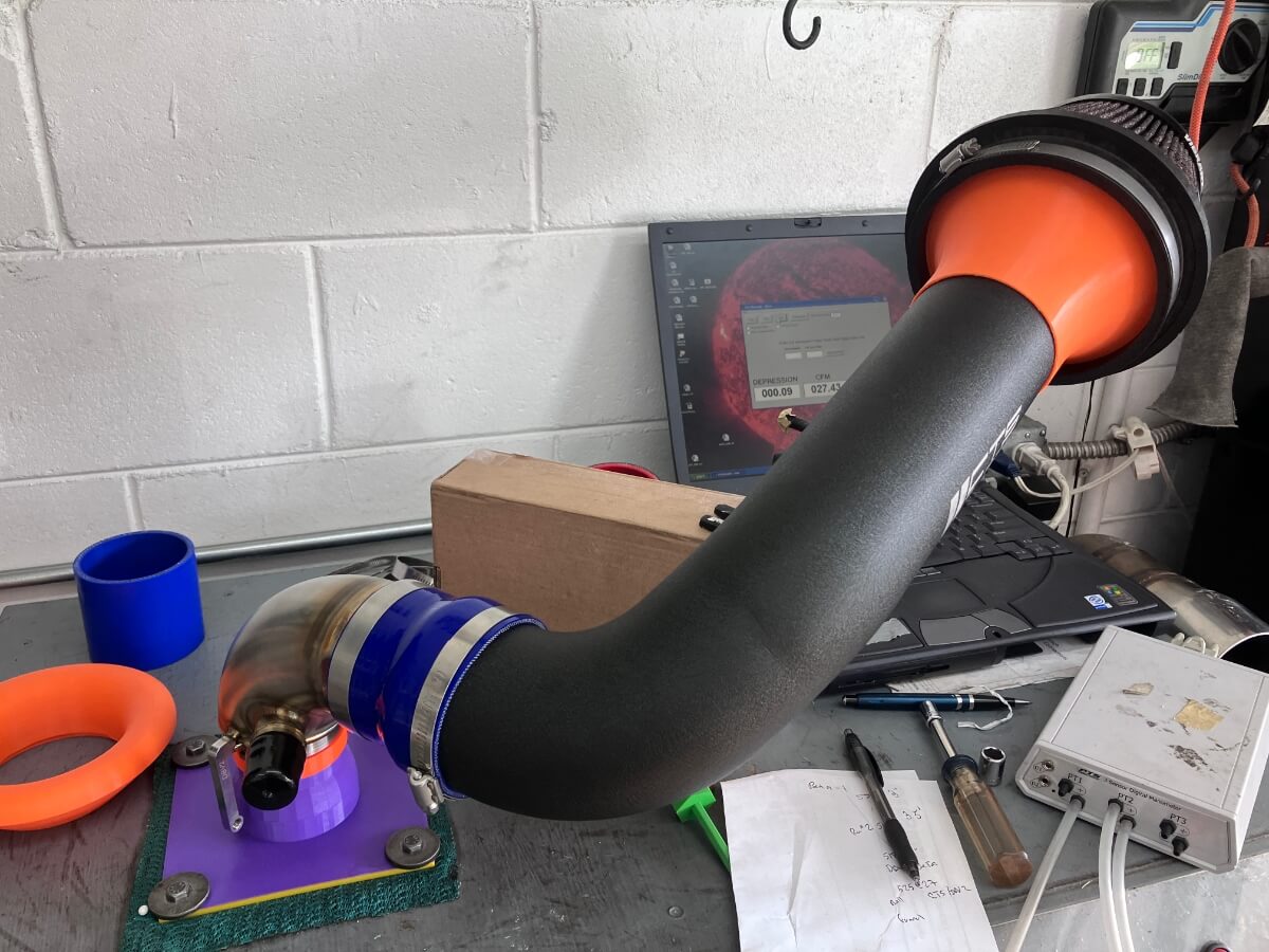
A final pair of tests were conducted with the CTS Intake and a DBV2 turbo inlet pipe (TIP) attached to a hybrid turbo adapter to see how this setup compares with other commercially available intakes.
The CTS intake is tested again using the funnel:
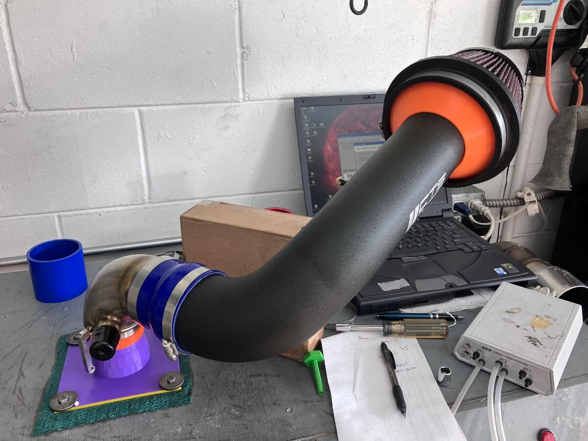
Then with the bellmouth:
Resulst are shown below compared with the other intakes that have been tested in this configuration:
Just use the EQT blaze intake. According to them, with zero evidence to back it up, it’s the best intake in the universe!
/S
It actually looks nice with that small bit of color. I wouldn’t even paint it. She making all the right sounds at least?
This was to get an idea of how much potential improvement might be made to an intake that is already very high flowing. The two adapters I made for the Vibrant filter to work with the CTS inlet pipe were only for the flow bench test, they aren’t designed to remain in place on an operating engine.
Yet
U forgot to say yet LOL but seriously, it genuinely looks nice
Thanks! I need to get the design fairly well refined before I’ll switch to printing it with a material that can withstand the heat in the engine compartment.