Background:
In the previous post on the MGM7 intake development, I discussed finding that the Beta-9 intake with a 3″ outlet flowed more than the Beta-10 intake with a 3.5″ outlet.
I guessed that this was because the Beta-10 intake maintained a large diameter until just before the transition to the turbo inlet elbow and that the transition to the elbow diameter was too short.
Beta-11 Development:
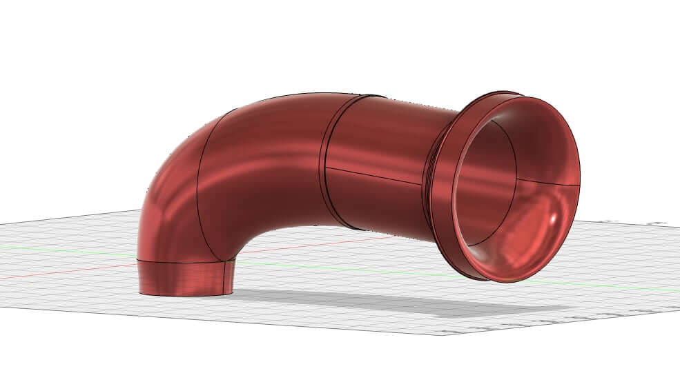
For the Beta-11 intake, I returned to the Beta-9 design and made some changes. The first was to increase the outlet to 3.5″ from 3″. Another change was to raise the position of the inlet end slightly relative to the position of the outlet end.
A small overlap was built into the straight portion of the intake to facilitate swapping in different design options without reprinting the entire intake.
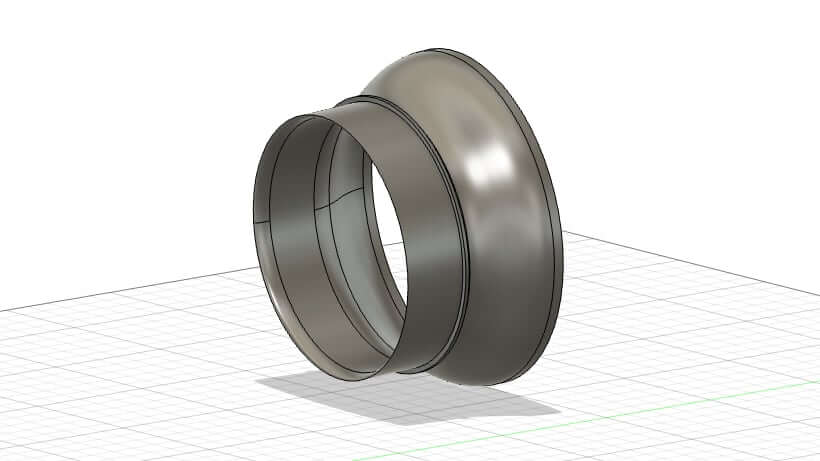
Another benefit of the modular build is that an adapter for a different filter can easily fit onto the intake. I made an adapter to attach the APR PEX intake air filter.
Flow Testing:
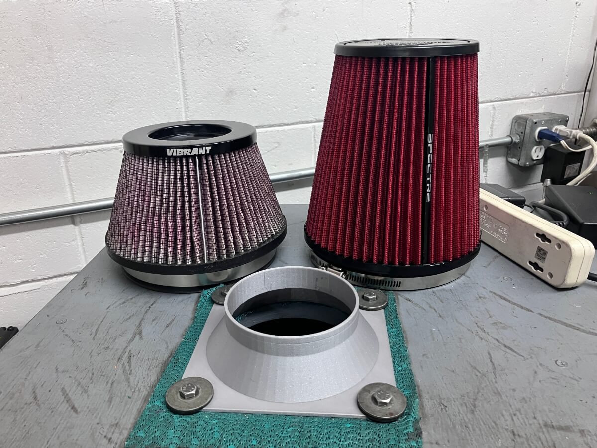
The parts were gathered for a flow test to see if the Beta-11 design improved airflow compared to the Beta-9 intake.
The Beta-9 would be tested first to set the baseline performance.
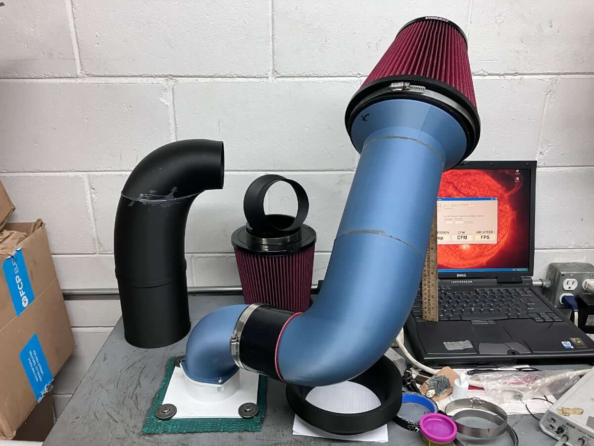
All intakes are tested using an inlet elbow with a 3.5″ opening and taper to fit the Mabotech M720 turbocharger.
Testing is conducted at 25″ of H2O, one inch less than in the previous test. If the Beta-11 intake flows appreciably more than the Beta-9, it may be nearing the bench flow limit of 600 CFM. Reducing the test depression will lower the flow rate and ensure the readings are within a valid measurement range.
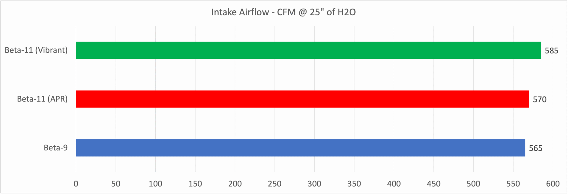
The Beta-9 flows 565 CFM @ 25″ of H2O.
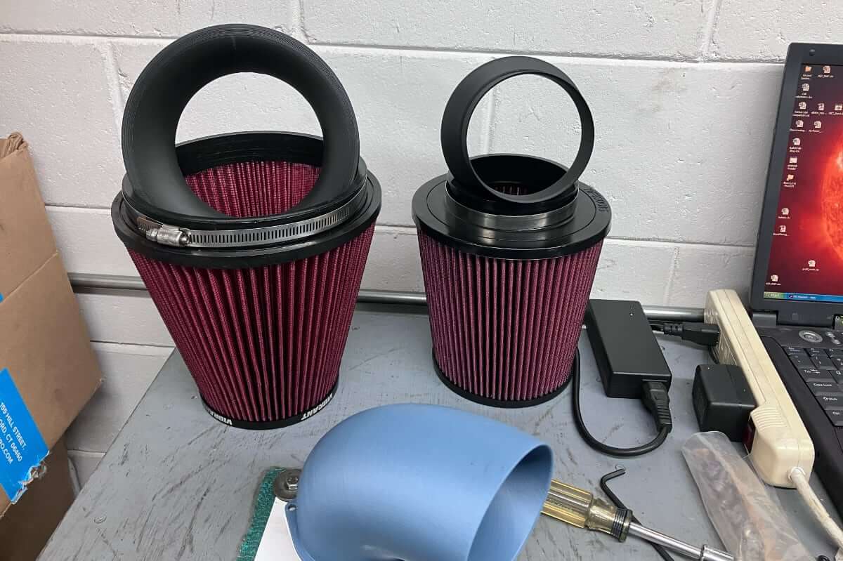
Next, the APR air filter is attached to the adapter and the MGM7 intake tube.
The Beta-11 with APR filter is then flow tested.
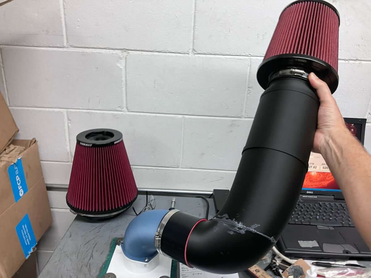
The Beta-11 with APR filter flows 570 CFM @ 25″ of H2O.
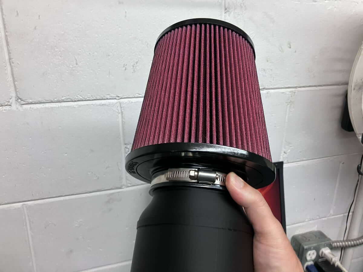
The Beta-11 intake is then fitted with the Vibrant air filter, the part it was designed to use and flow tested.

The Beta-11 intake flows 585 CFM @ 25″ of H2O.
The results are shown together in the following chart:
Test Fitting:
The next activity is to test the fit within the engine compartment.
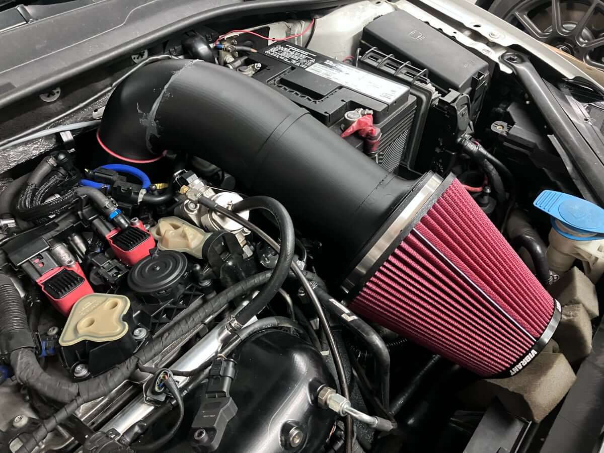
Clearance at the rear of the intake is good.
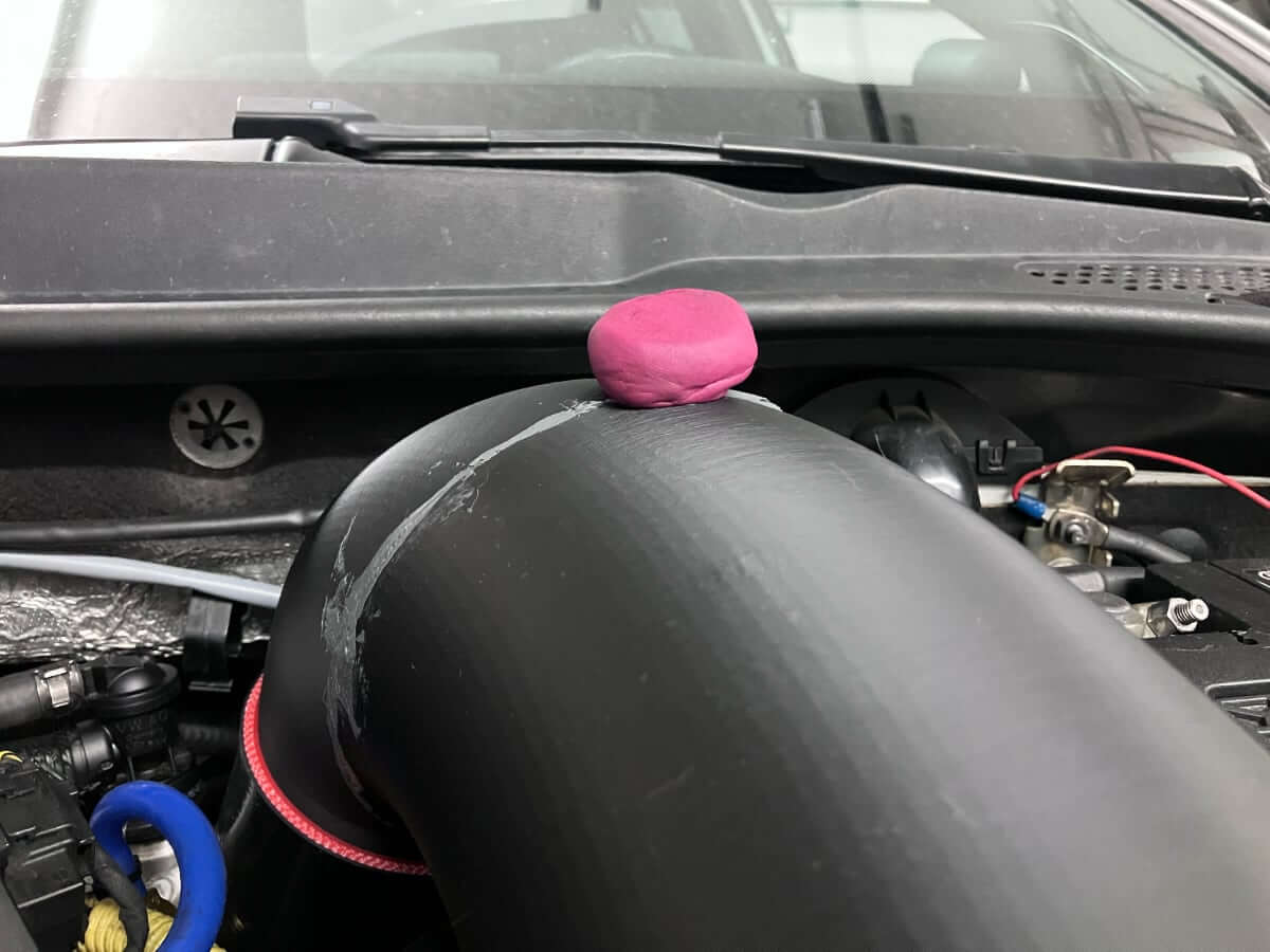
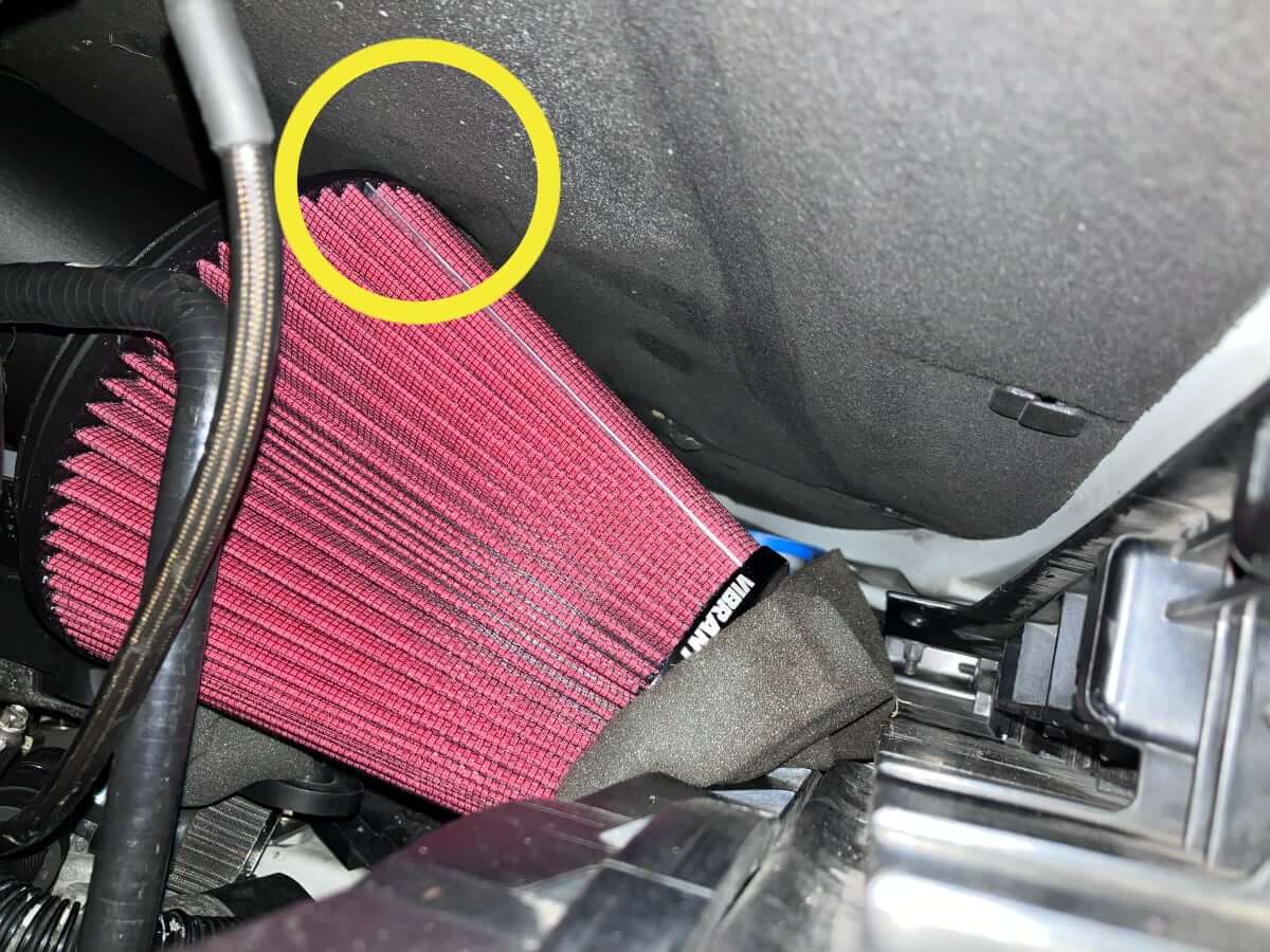
The upper edge of the Vibrant air filter is another location that is close to the hood.
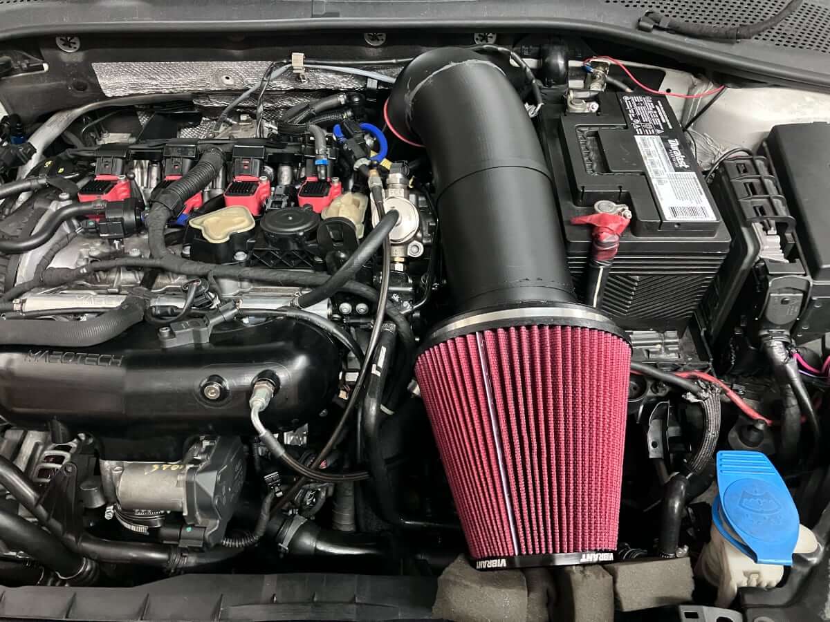
There’s room, though it is close.
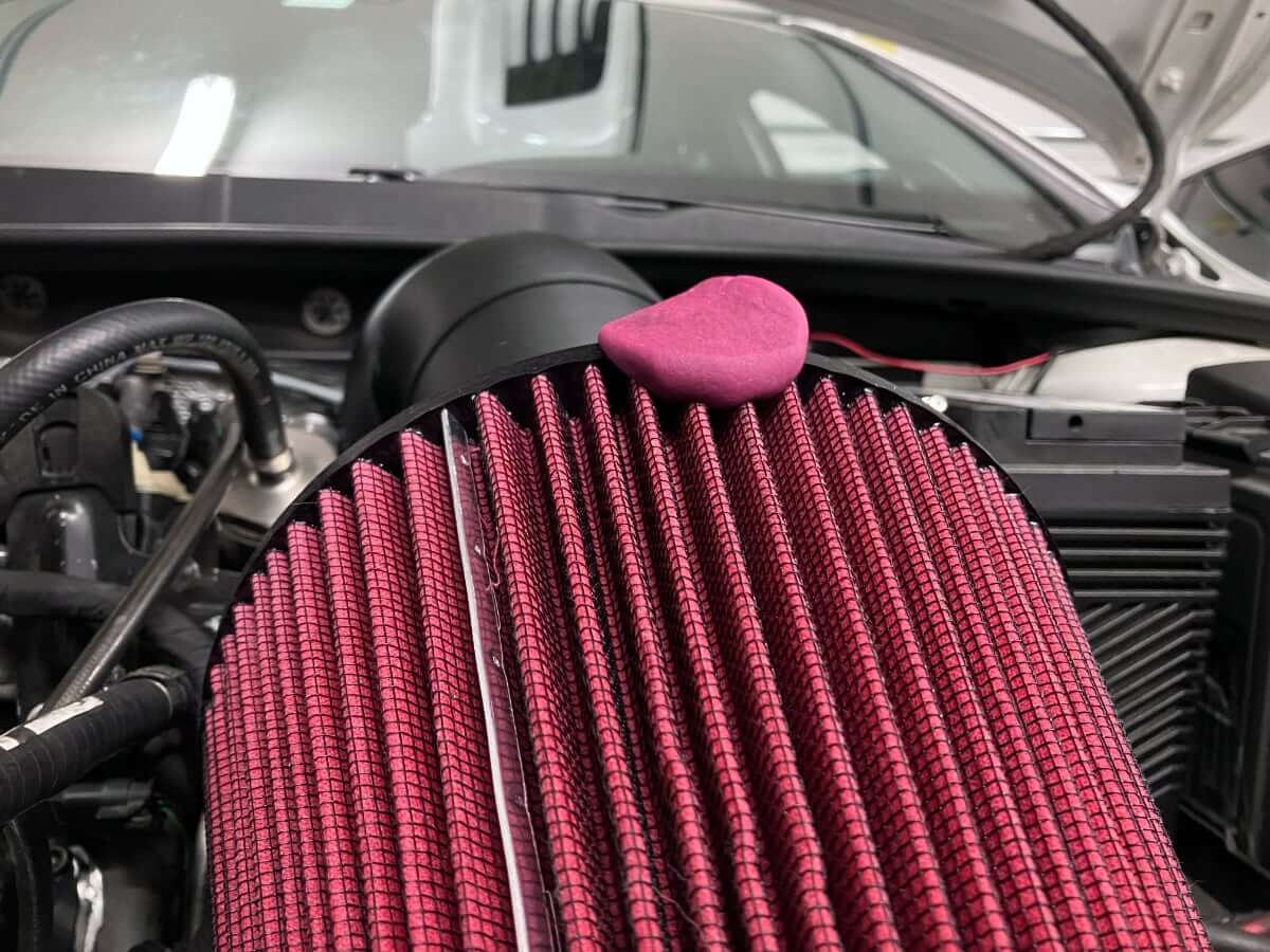
Taking a picture of the air filter with the hood closed shows how the location checked with the Play-Doh compares with other sections of the air filter.
Next Step:
I’ll work on lowering the air filter by approximately 1/2″ to provide some more clearance between the hood and the base of the air filter. I’m also going to shorten the length of the intake by approximately 1/2″ to bring the base of the flange closer to the airbox support post on the battery tray. That should provide a good location to build support to hold the intake in place.
I am also considering reacquiring the Vibrant 6″ filter I used for testing. I’d like to find out how much different the 6″ filter flow rate is from the 7″ filter I currently use since a smaller filter is easier to fit within the engine compartment.