
Background:
What about that air duct?
In a previous post, I mentioned that I had noticed some abnormally high turbocharger compressor outlet air temperatures recently.

More typically the peak temperatures with my IS38 turbocharger are about 50 degrees Fahrenheit lower than what recent temperatures have been.
I speculated one possibility was that I had not properly installed the partition around the CTS intake and that more air from inside the engine compartment was being drawn into the intake.
When I have looked at the CTS intake in the past I found it did create slightly higher air temperatures in the turbocharger, but the rise in the compressor outlet temperature seemed out of proportion to the intake temperature increase.
After looking around more closely I realized that the stock air duct I was using was an unmodified stock duct. I have two “stock” air ducts, one is in original condition and the other has had the front on the driver’s side opened up, and the rear on the passenger side is closed.
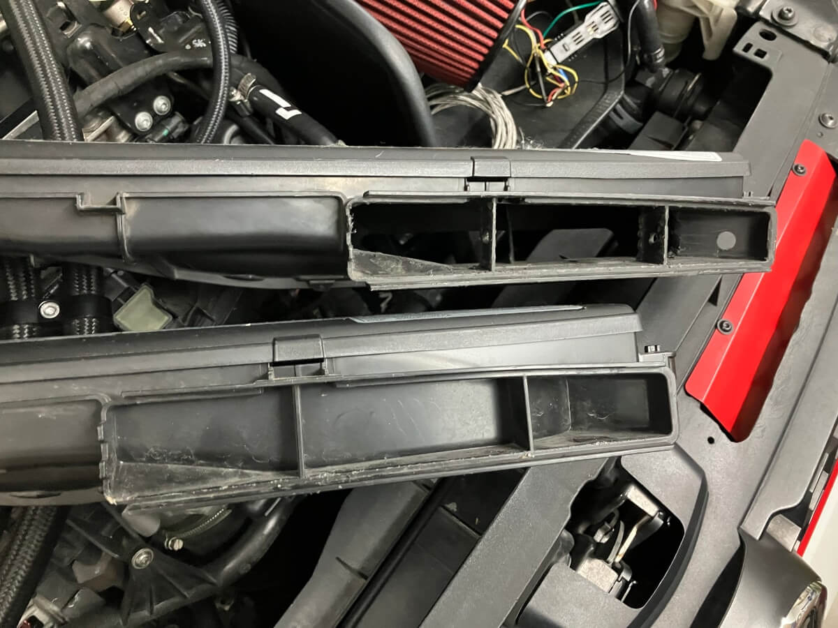
This completely stock duct seemed like a good candidate to explain the increased air temperature, compared to when I used a closed intake.
To find out what is going on I need to measure the air temperature entering the turbocharger.
Test Process:
To find out if the stock air duct is the cause of the higher turbo outlet temperature I need to install a temperature sensor in the turbo inlet pipe (TIP). I have a TIP already set up to support this, but due to space limitations, the Forge BOV needs to be installed to make room for the temperature probe.
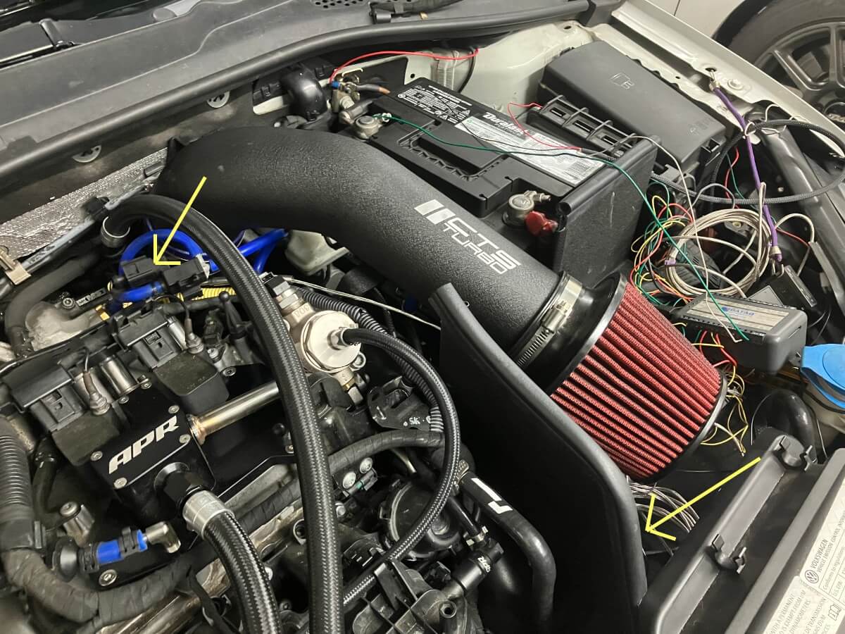
The Forge BOV was installed and then a temperature probe was inserted inside the TIP.

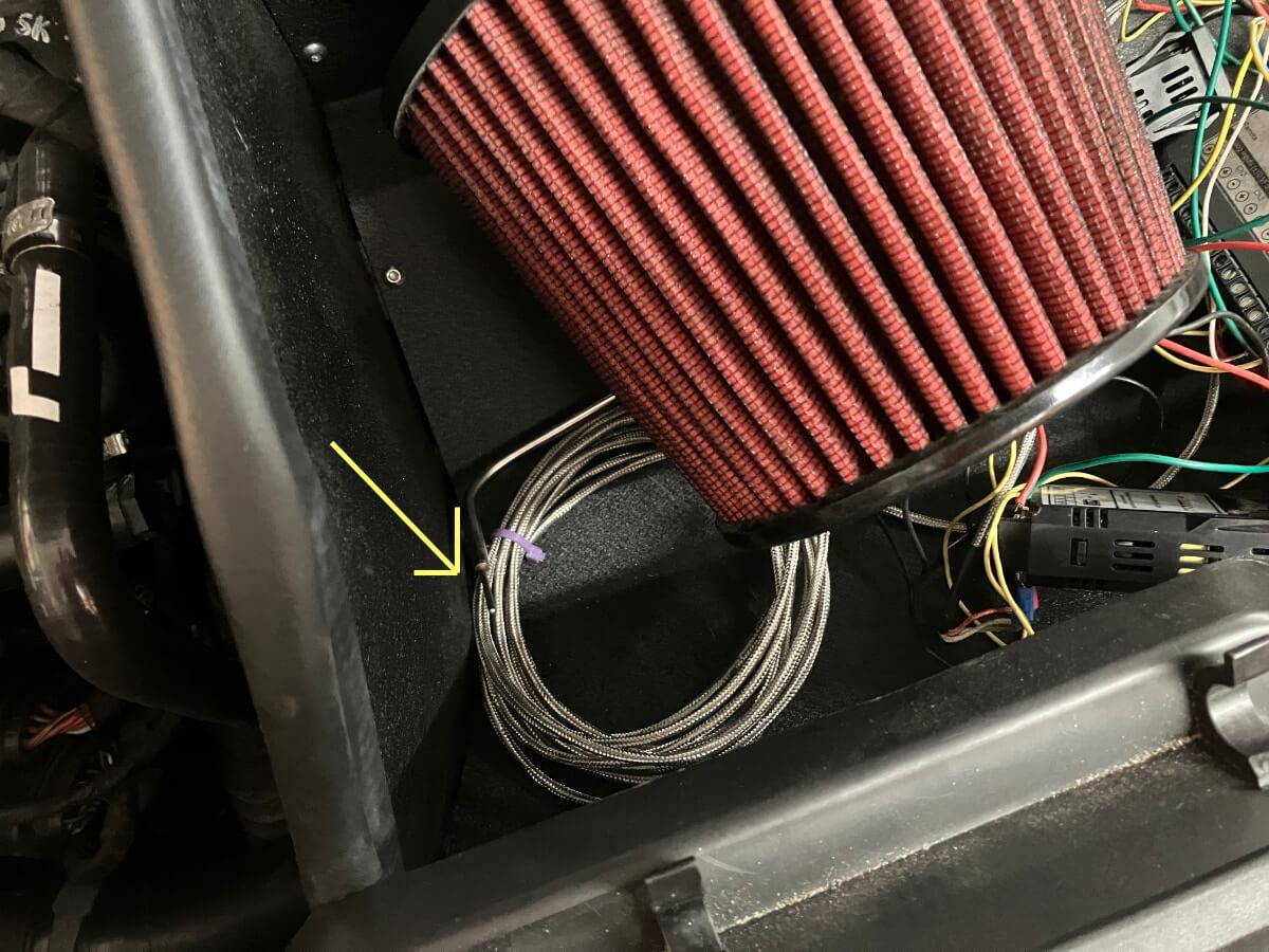
A second air temperature sensor was placed near the air filter. The locations of these temperature sensors are indicated with the arrows in the pictures above and below.
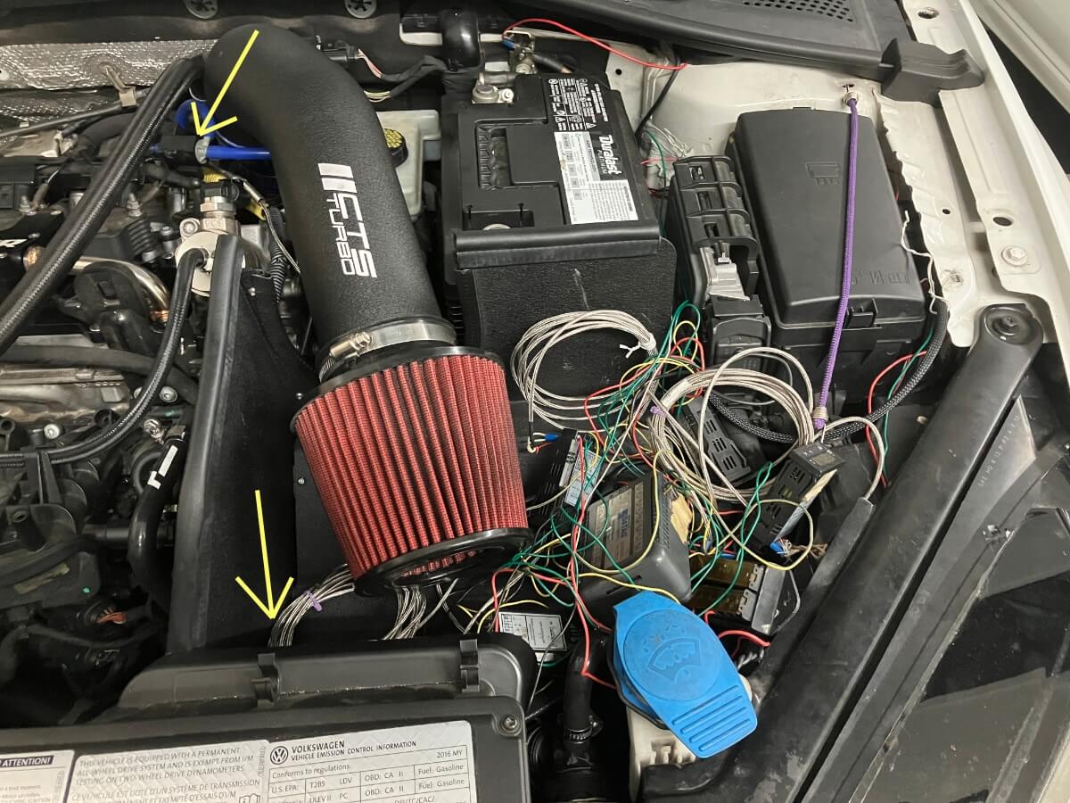
The sensor near the filter is to help understand the air temperature in this area. There are more options for placement near the air filter, but the temperature at this location is less important to the experiment, which led to placing the sensor on the partition near the bottom because this was easiest for placement.
The completely stock duct will be referred to as “Duct-1” and the stock duct with the front of the driver’s side opened, and the rear of the passenger side open, is referred to as “Duct-2“.
Test Results:
Two types of drives are made for comparing measurements. The first drive is to an area where I can make a few full-throttle acceleration pulls and the second is an in-town out-and-back drive that I make regularly.
The focus of the first drive is the measures under full-throttle conditions. The second drive will be a comparison of lower airflow demand driving but with a better match of vehicle speeds and operating time.
In addition to the air temperature at the air filter and the turbocharger inlet all of the charts include the ambient air temperature and the vehicle speed.
The full-throttle acceleration charts also show boost pressure.
Duct-1:
The entire session during which the full throttle data was collected is shown below:
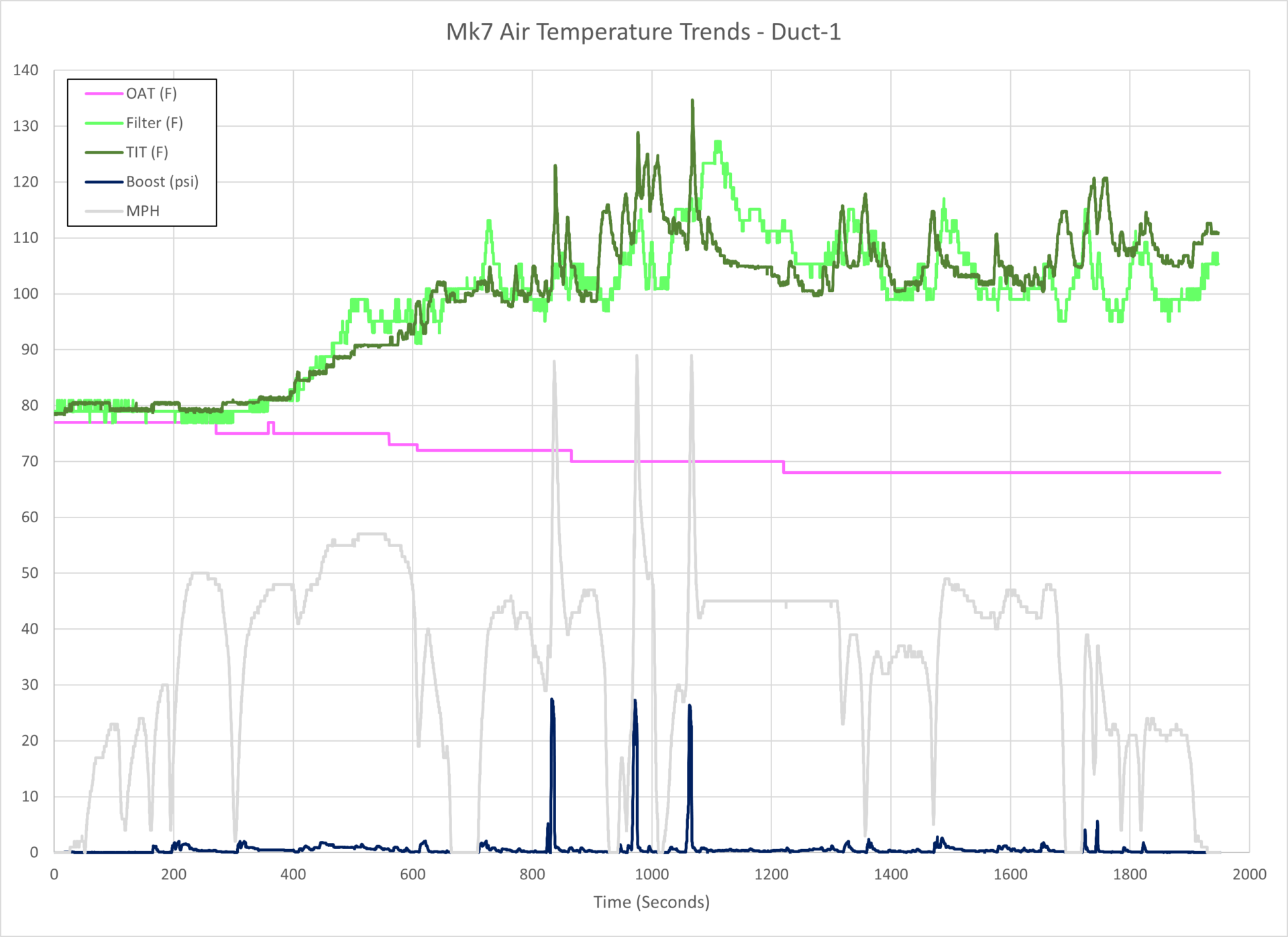
The next chart is a close-up of the three full-throttle acceleration pulls.

The turbocharger inlet air temperature (TIT) rises steadily during the acceleration, shown by the red and blue arrows on the chart above.
The turbo inlet temperature also increases with consecutive pulls; 113F, 118F, and 123F.
Of note is that the turbocharger inlet air temperature is rising faster than the air temperature at the air filter sensor location (Filter).
My theory for this is that the air filter is drawing air in from all around the filter and the outside air from the duct is passing along the bottom of the airbox partition and being drawn into the lower portion of the air filter. This is keeping the air filter sensor in relatively cooler air.
If warmer air from the engine compartment is being drawn into the air filter from the upper portion of the air filter, it would then mix with the cooler air from the lower half, and the mixture would be at a higher temperature than what the air filter sensor is measuring.
If the air demand increases, a larger portion of air may be getting drawn in from the engine compartment versus the outside air through the duct.
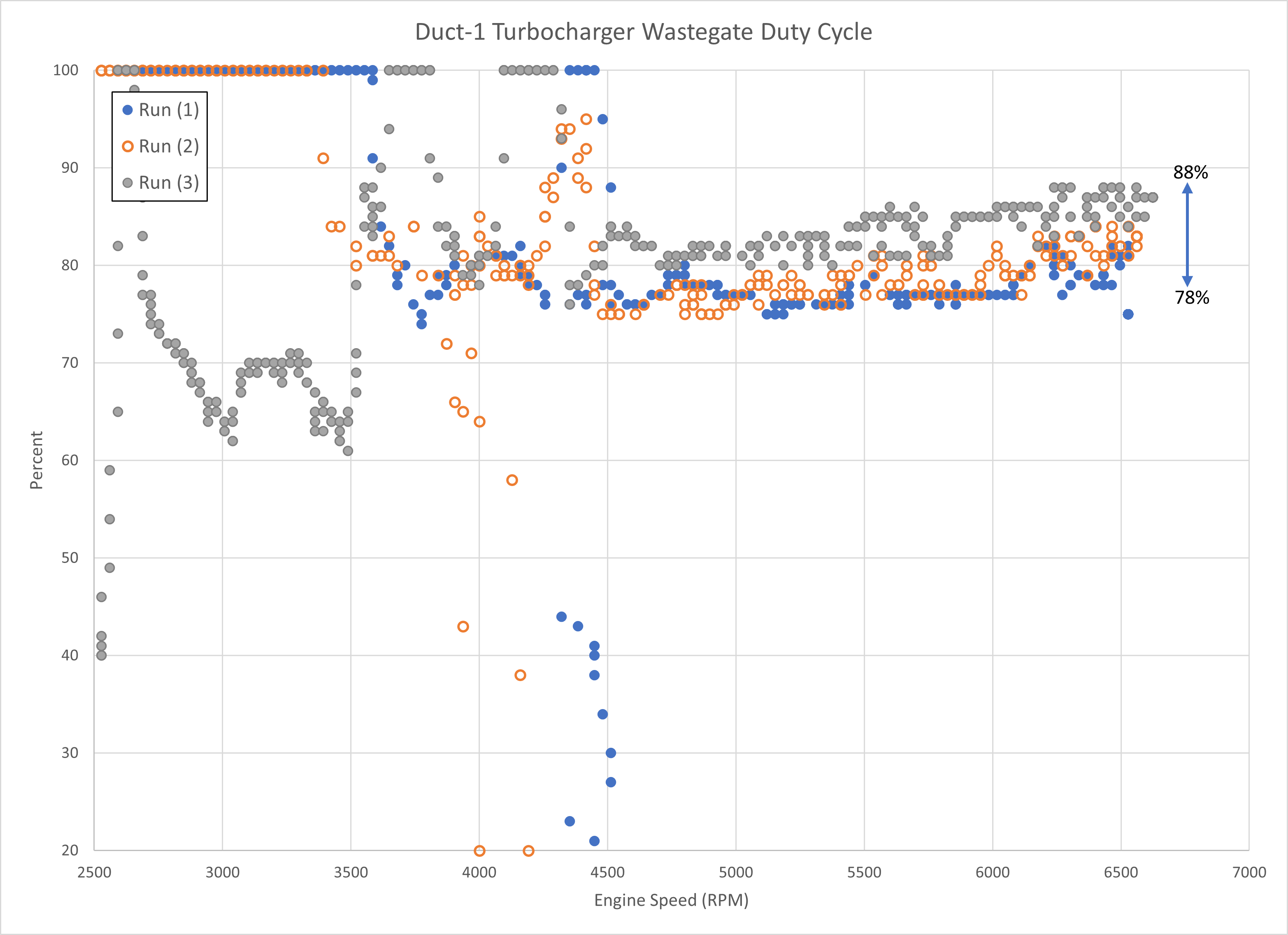
The next chart shows how the turbocharger wastegate duty cycle increase with the increase of the turbocharger inlet air temperature on subsequent pulls.
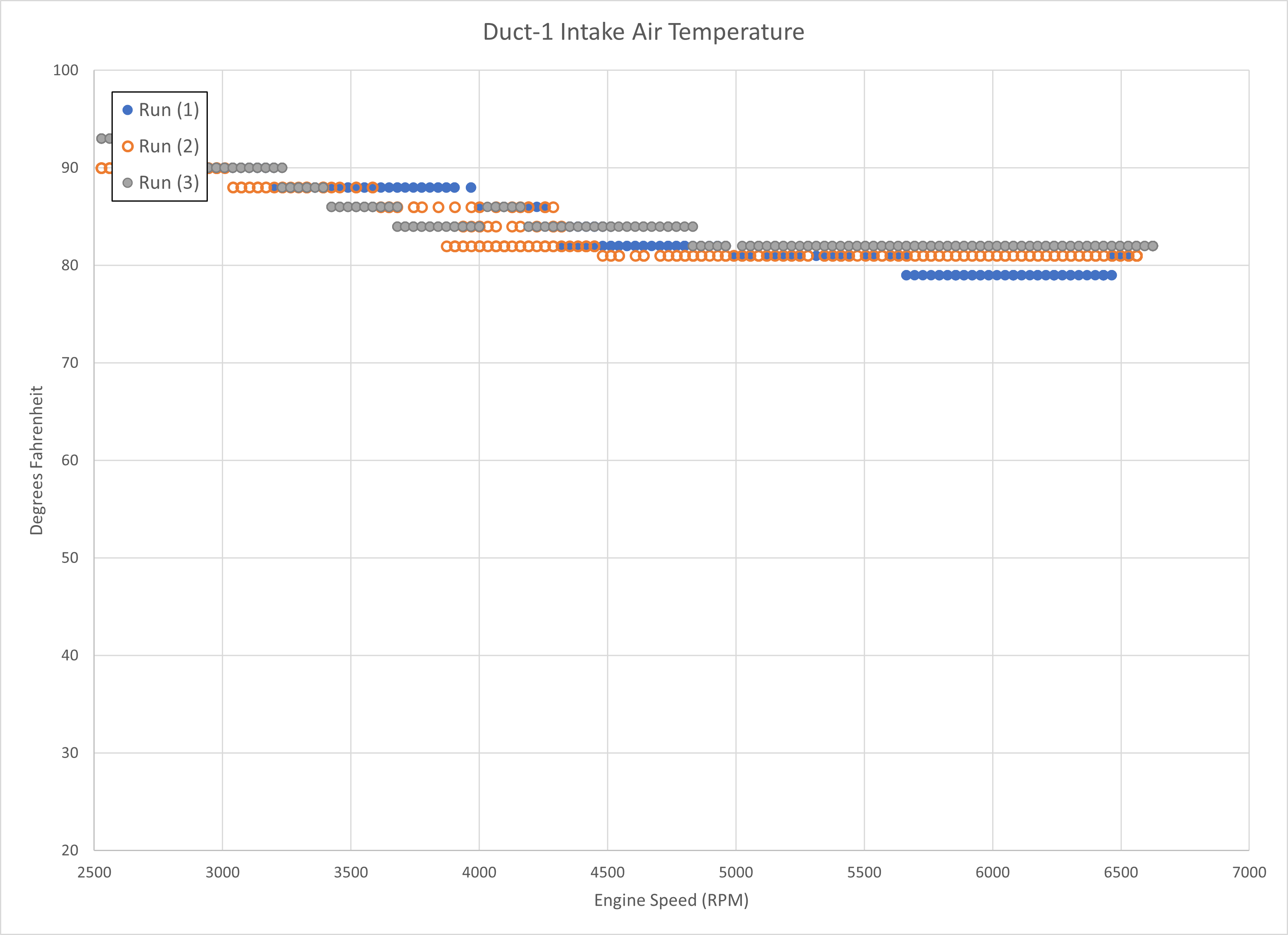
The next chart shows the Intake Air Temperature inside the intake manifold during these pulls.
Even though the temperatures are rising at the turbocharger inlet the Intercooler is maintaining a steady output air temperature.
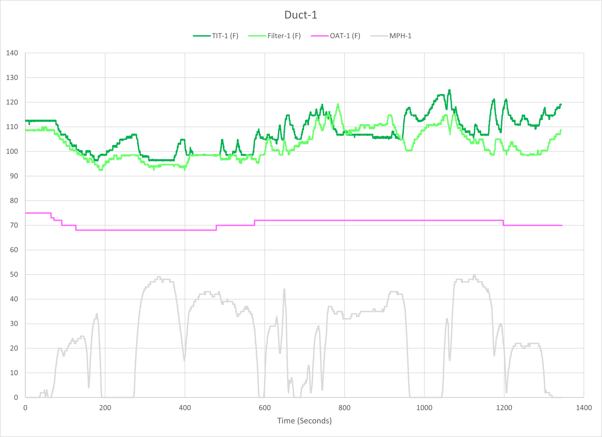
The next chart shows the air temperatures during the out-and-back drive.
This drive was made a couple of hours after the acceleration pulls which is why the initial air temperatures are elevated above ambient air temperature.
Duct-2:
Next, the air ducts were swapped so that Duct-2 with the opening on the driver’s side is being evaluated.
On the charts, the solid lines are for Duct-1 and the dashed lines are for Duct-2.
The out-and-back drive was repeated and the temperatures using Duct-2 are shown below:
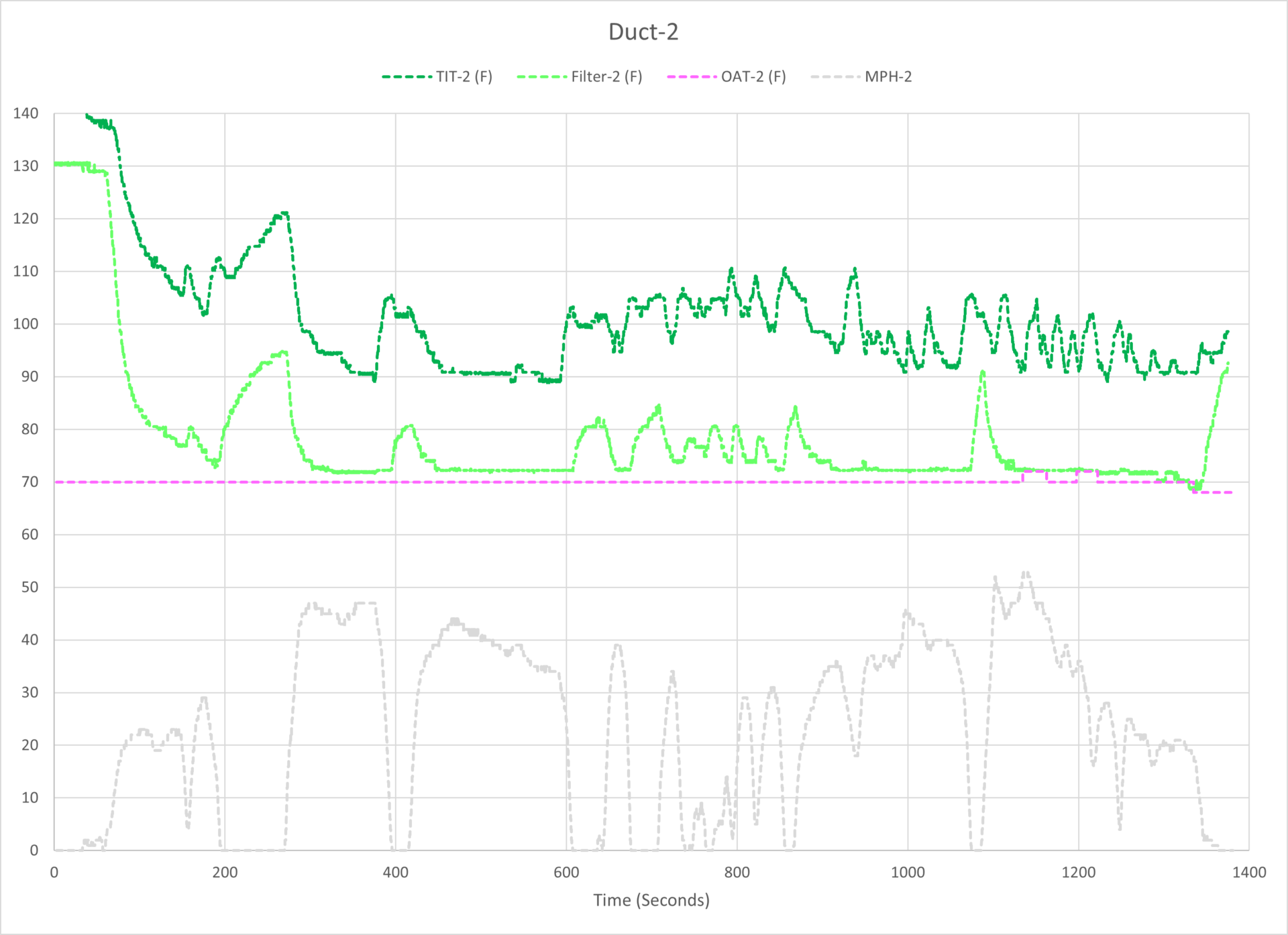
Most apparent from the chart above with the air Duct-2 is the air temperature recorded near the air filter remaining closer to the ambient air temperature.
The next chart compares the turbocharger inlet air temperatures using each air duct.
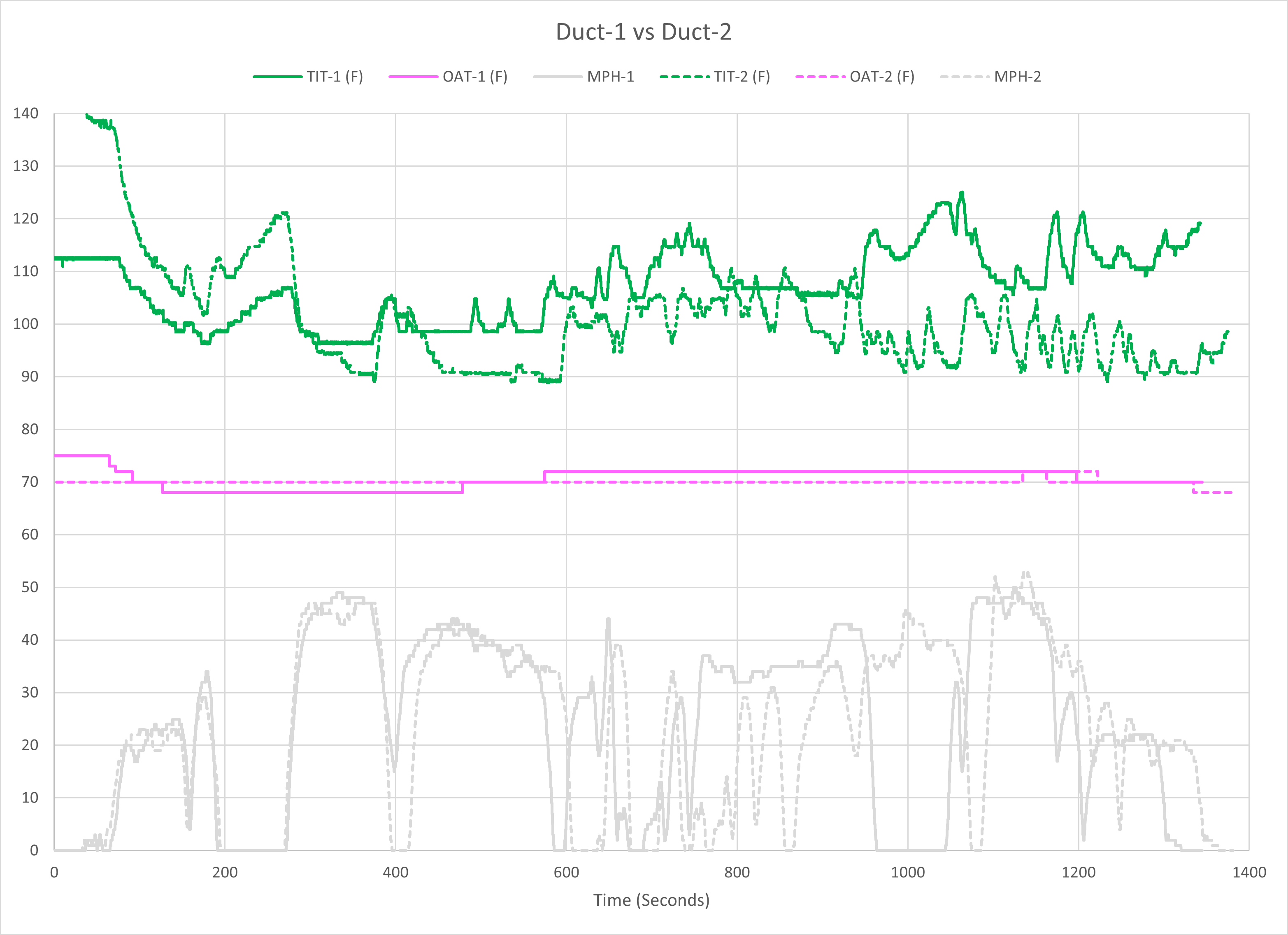
The Duct-2 shows a small decrease in the air temperature at the turbocharger inlet.
Next, the temperatures at the air filters using each air duct are compared.
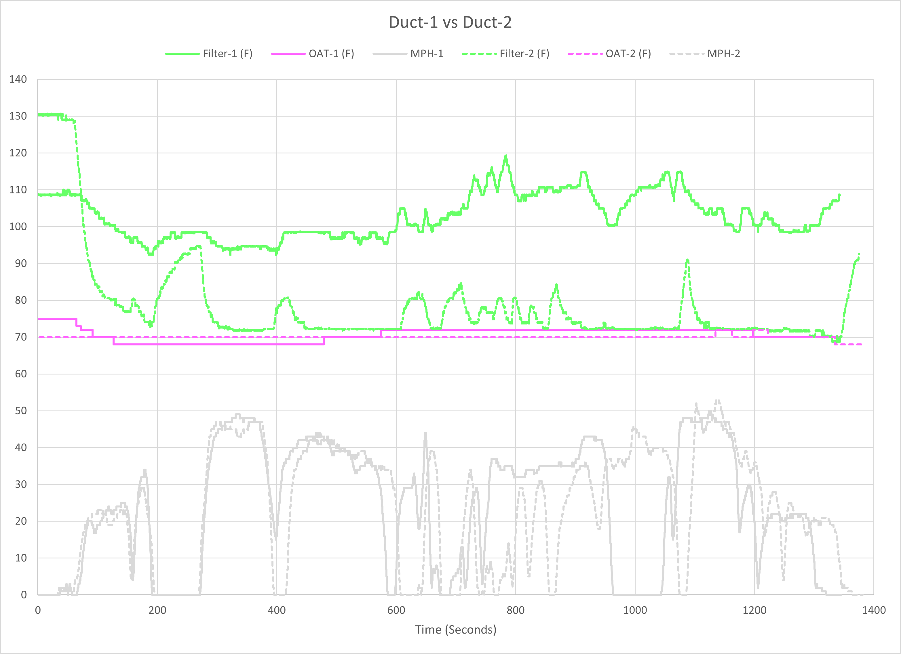
Air Duct-2 shows a significant decrease in air temperature at the air filter sensor.
Conclusions:
A completely stock GTI air duct was used during full-throttle acceleration while recording air intake temperatures and during a low-speed out-and-back drive around town.
During the full-throttle acceleration, it was observed that the air temperature entering the turbocharger increased steadily during a pull and with consecutive pulls.
The increase in turbocharger inlet air temperature is correlated with an increase in the turbocharger wastegate duty cycle while Intake Air Temperatures remain approximately constant.
A modified stock air duct was installed for an out-and-back drive and a significant drop in air temperature at the air filter was observed. A less significant drop in the turbocharger inlet air temperature was also observed.
Next:
Measuring air temperatures using air Duct-2 during full-throttle acceleration will be the next step of this experiment.
Great work. Certainly seems to verify (and enhance) your past tests with the duct block-off plate.
Thanks! This time around I was interested in getting a better idea of what can be done to help the air temperatures when beginning with a completely stock part.