
Background:
Continuing the design evolution of an intake, in this post I discuss the latest version.
Beta 2:
A key question that came out of the first beta intake test was if increasing the outlet diameter would improve airflow. This was presumed to be the likely outcome, but making the part and then testing it was needed.
Shown below is the next iteration that incorporates a 3.5″ diameter outlet.
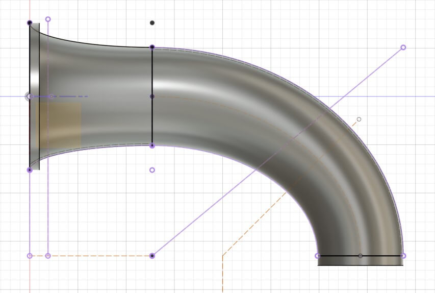
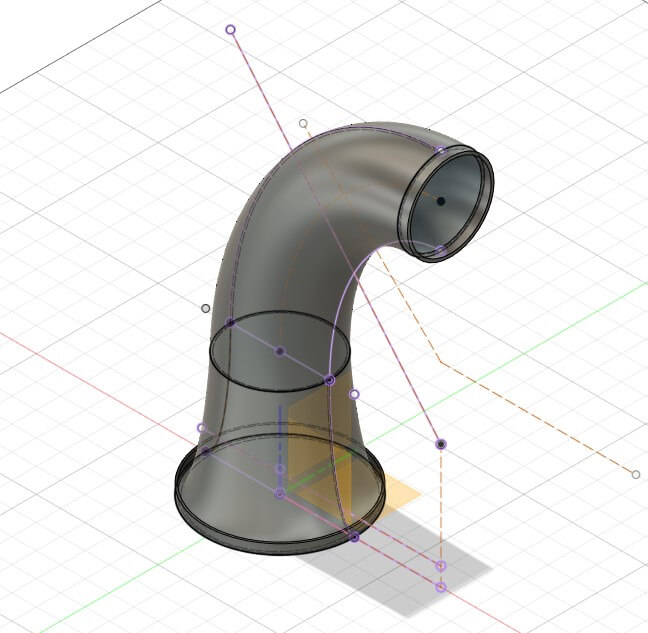
CFD analysis of the design shows a similar flow pattern to the first design with slightly lower velocity.

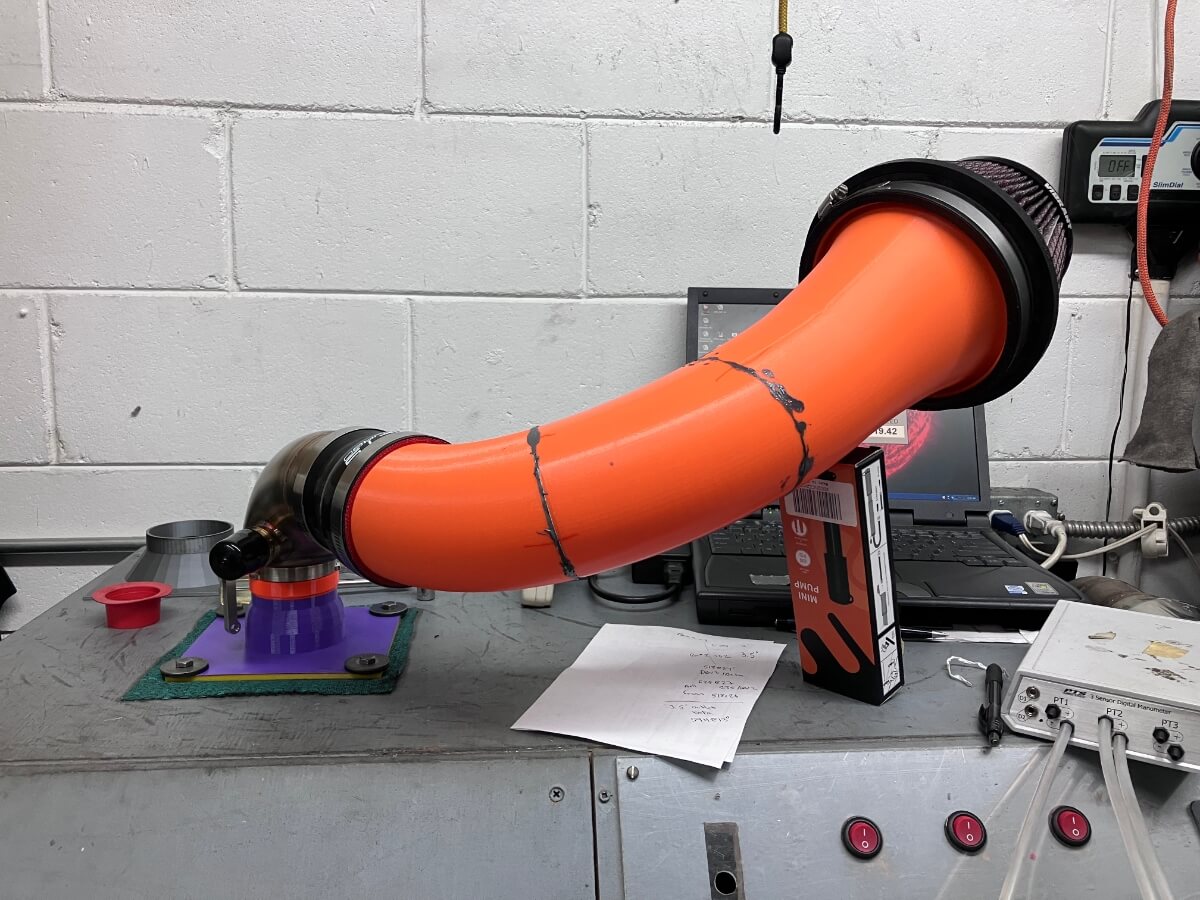
Test setup:
The new design is attached to the flow bench using a silicone hose that transitions from 3.5″ to 3″ and a 3″ adapter.
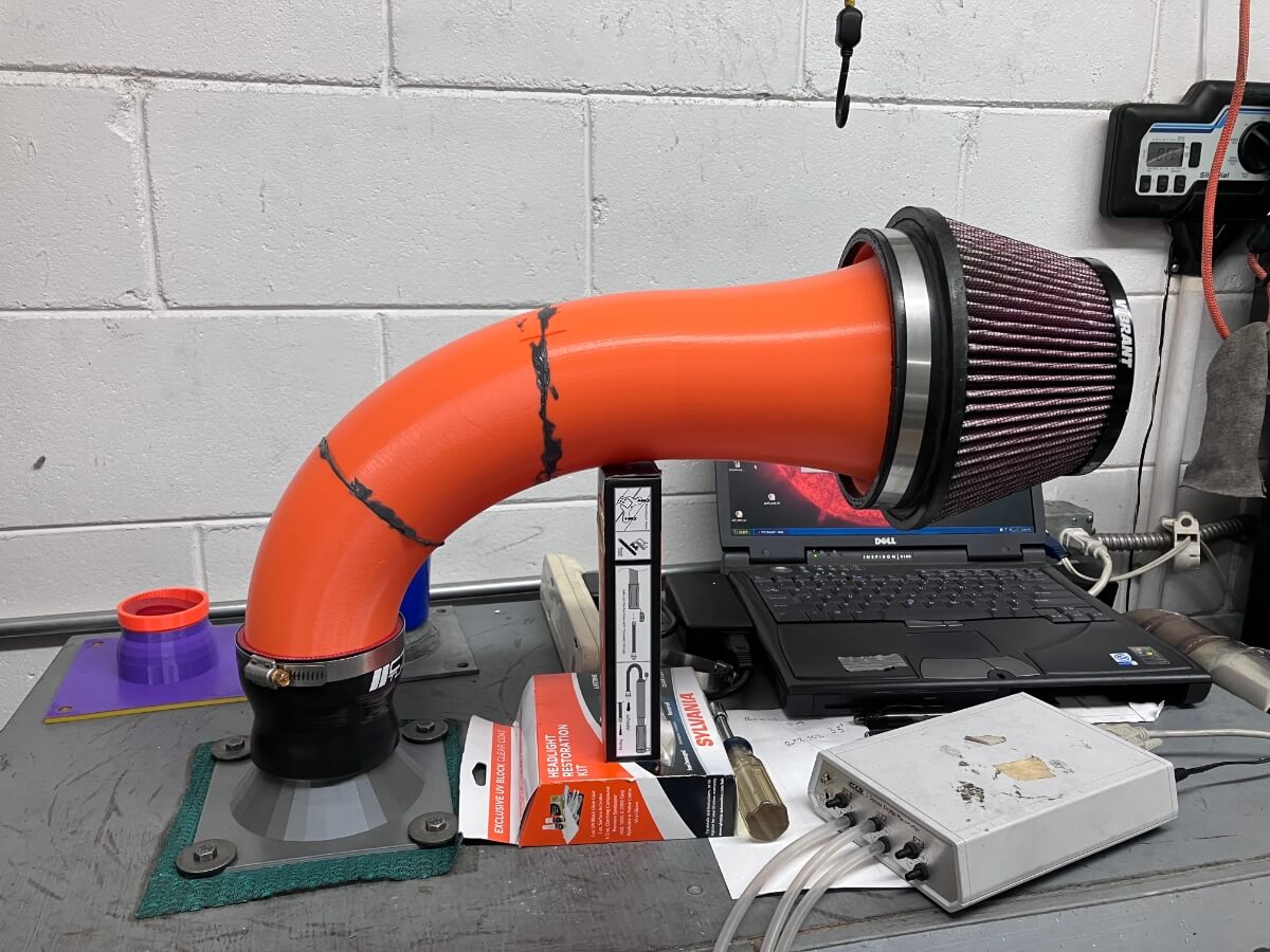
A second measurement is made with a DBV2 turbo inlet elbow attached to the intake and the elbow attached to the bench using an adapter that simulates a hybrid turbocharger compressor inlet.
Test results:
When connected directly to the flow bench the intake flows 594 CFM @ 13″ of H2O.
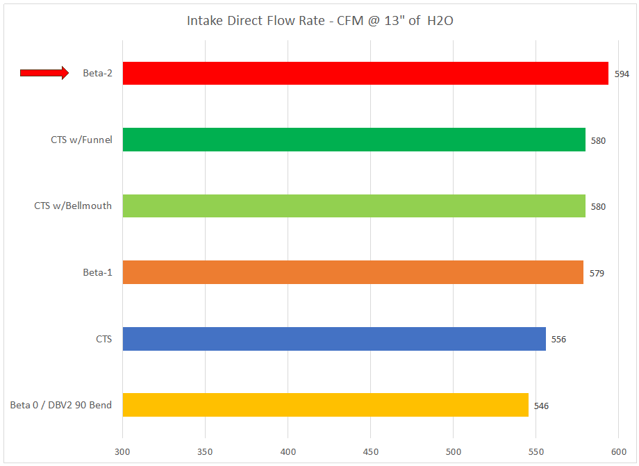
This is a 6.8% increase versus the CTS Turbo intake (556 CFM @ 13″ of H2O) tested as sold.
Progress Check:
The flow rate through the beta intake is shown compared with several commercial intakes.

Note: The test depression is 13″ of H2O which is approximately 50% of the pressure that I usually test using when including the turbo inlet elbow. Removal of the TIP increases the airflow through all of the intakes substantially.
TIP Effect:
Shown below is a comparison of flow rates when the TIP is connected and without the TIP.
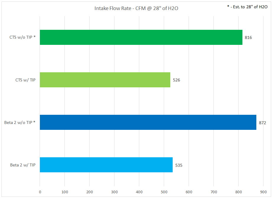
Note: The flow rate of the intakes with the TIP removed is estimated for the test pressure of 28″ of H2O. This is because the flow rates exceed the flow bench maximum of approximately 620 CFM @ 28″ of H2O.
Conclusions:
Flow testing of the Beta-2 intake which incorporates a 3.5″ diameter outlet shows a 15 CFM gain versus the Beta-1 intake.
Question, would you ever sell the completed final version as product to consumers? Really interested in this design.
When I get it finished, I’ll make the design available to others somehow. I haven’t given much thought to what comes after I finish since I have a way to go yet.
Would be great to see this come to market. Any ideas on what you’ll do to avoid making this a “hot air intake” ?
I plan to work on a heat shield after getting the intake design set.
What TIP did you use for this test? Without there’s basically a 50CFM gain but with the TIP only 10CFM gain.. Wokder if it’s worth the effort for the smaller gain there. Wonder if a hybrid turbo setup would change this at all..
In the second paragraph of the test setup section, it is stated that a DBV2 TIP is being used.
I doubt that the gains are worth the effort on any setup that uses an inlet adapter (TIP or flange like Revo and Blaze) that reduces the cross section significantly from that of the intake.
For me the design is a fun project to use to learn more about the CAD software I have and perform more experiments comparing the intake to the commercial products.
Sorry Jeff I missed that information in relation to you using the DBV2 TIP for that test. What’s your thoughts on the look of the Garrett powermax stage one turbo TIP? Garrett run there own design and it runs a gasket not like the standard TIP design..
I was thinking of running a mode design performance intake. Or making one the same. They run a 4” intake pipe no bends that’s up 0.5” on the CTS intake. Then I’ll run a 6” bellmouth with a 6” tall filter you recently tested. This setup should be ok I thought and flow abit better then the CTS setup?
I’ll be running roughly at 400HP on E85 on the powermax stage 1 turbo. I don’t no the calculation to work it out. But do you no how much power roughly I would gain from 10CFM? I’m assuming this is what I’ll gain on this kind of setup over the CTS.
I had a Garrett elbow for a while that I ran a test with (Garrett size specs). I didn’t publish the results since the design is unique to the Garrett turbo. With a 56 mm outlet it is similar to the DBV2 TIP and Blaze flange in terms of size at the outlet, but the inlet is slightly smaller than the stock TIP. It measured 470 CFM @ 28″.
Based on the outlet size I think comparing it to the elbows I’ve tested using a hybrid adapter is appropriate. In comparison, that flow rate is better than the elbows made for use with stock turbos, but less than elbows made for hybrid turbos. My guess is the relatively small inlet is the main factor behind the difference.
My guess is that a 10 CFM difference at 400hp is maybe a 2hp power difference.
What’s your thoughts on improving the inlet sides of things on the Garrett TIP? Outlet seems good. But wanna improve the inlet somehow..
It is sized to work with the stock accordion hose, if the inlet end were larger that should help improve airflow rate through the elbow. At least that has been the case with other elbows I’ve tested, having an opening closer to 3″ has correlated with higher airflow, as long as the outlet is also larger, which on the Garrett elbow it is.
Yeah that’s my thoughts. Any ideas on how I can achieve this or Mabey get something made up? Thinking of some possible options.
I believe Blaze made a variation of their turbo inlet flange to fit on the Garrett turbo. You’d then need to use their silicone hose, or source one that fits from the turbo to the intake. I’m not aware of any other elbow options for the Garrett turbo.
Hey Jeff. I did suss out your reviews on the 4” open pod blaze setup flowing about 490CFM still abit down on the CTS with a hybrid adapter. Definitely surprising considering the blaze is basically a 4” straight pipe that goes to 3” to the turbo inlet I don’t see why it flows 30,40CFM less then the CTS but it’s definitely interesting. If that’s the case might get a custom 3” turbo inlet made up for the CTS intake..
On the face of it the Blaze appears to be that, a 4″ straight pipe going to a 3″ inlet, but it’s in the details where I believe it incrementally drops down in performance. For example, the choice of using an inverted cone filter, as this test showed, brings an airflow penalty. There are other details that are worth reviewing, but a post dedicated to the topic would be better than using the comments section.
Hey Jeff
I found an intake called mode. It’s a 4” intake with a slightly straighter pipe then a CTS intake. What’s your thoughts on this intake vs the CTS? Looks like the mode intake might sit slightly lower in the engine bay vs CTS and sits slightly closer to the radiator also. Thought it might be a worthwhile upgrade with a 0.5” upgrade size in pipe and running a custom 3” TIP for my Garrett turbo. Link below for the mode intake.
https://modeautoconcepts.com/products/mode-design-performance-intake-kit-v2-0-suits-vw-golf-mk7-gti-r-audi-s3-8v
Ricky
Hey Ricky,
I think if you’re able to use a custom inlet elbow that allows for a gradual transition from the 4″ pipe to whatever size turbo inlet you have that the Mode may be a good product. In it’s form as they are selling it I’d be very concerned about that transition coupler from 4″ down to 2.75″. That has a strong potential to disrupt the airflow since it is a rapid necking down, but it seems that won’t be the case for you. It also looks like there are three direction changes going from the inlet pipe to the TIP outlet, that’s something new to me and I don’t have a basis for estimating how well that will work, though again, if you’re customizing your inlet elbow that might be less of a concern. It looks like a good starting point to work from.
Hey Jeff
I end up purchasing a blaze RHD 4” intake with with powermax flange adaptor. It didn’t come with a gasket. Are these ment to come with gaskets?
Ricky
I don’t know what that adapter is supplied with.