
Background:
In the first post discussing my effort to see if additional performance can be obtained from an intake, what I am calling the MGM7 intake, I flow-tested two different designs of pipe inlet transitions from a Vibrant air filter to the CTS turbo inlet pipe.
The results were positive, leading me to think some more about how an intake could be designed.
Motivation for effort:
Seeing if I could improve on the existing intake options available for the Mk7 GTI seems like a fun project. I reckon I have a decent shot at success because a few factors are working in my favor.
- Availability of Fusion 360 for 3D modeling
- Access to Simscale for basic CFD
- Work as a T&E professional with a background in aero and mechanical engineering
- Having a 3D printer and flow bench to go from a design concept to a physical prototype, to having test results in a relatively short time

The rapid cycling of feedback into the next prototype helps with improving the design.
MGM7 Intake Prototyping:
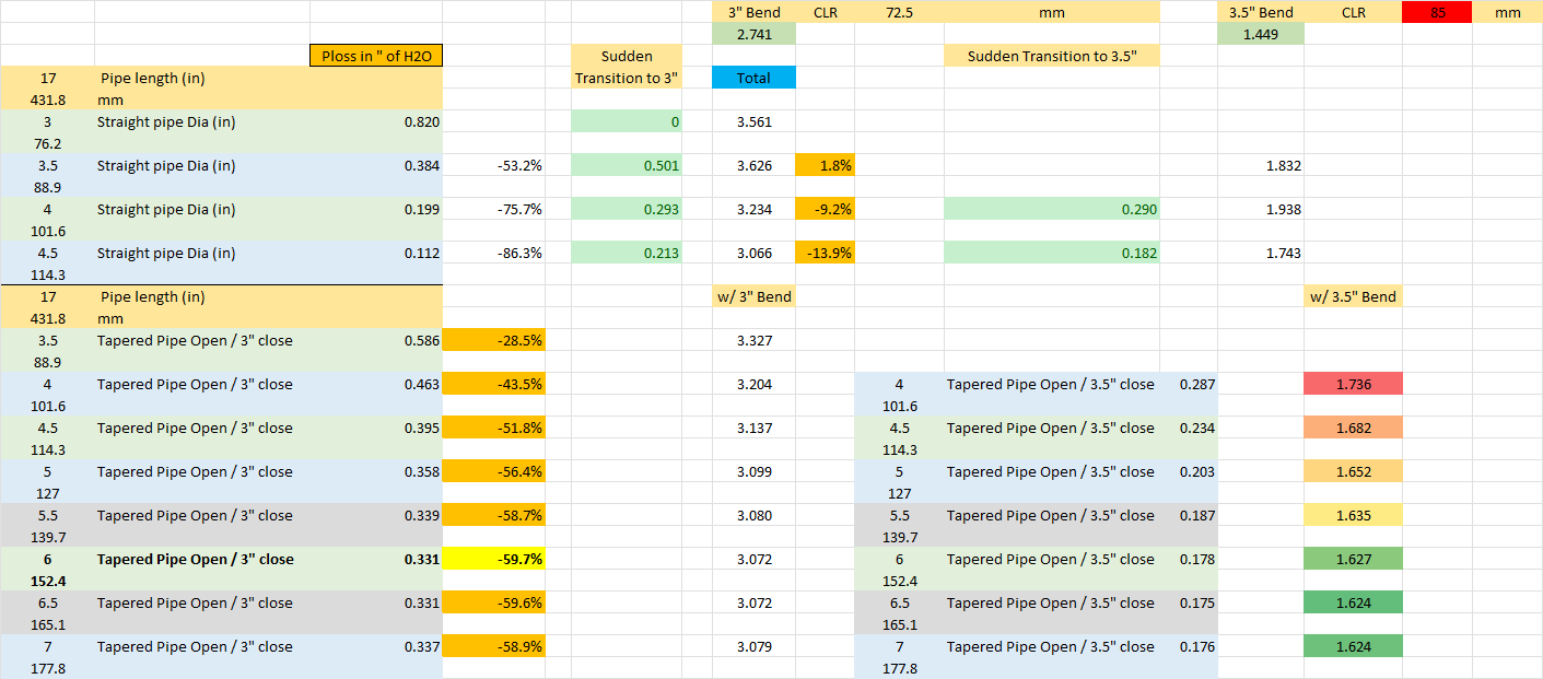
The first step I took was a numerical analysis of different alternatives of the major design elements.
Starting with some basic concepts about efficiently transferring air, keeping it on a straight path, and having a lower velocity so that friction losses are minimized, guided the first options which are variations on the “filter on a stick” style.
Filter Orientation Sidebar:
Why start with a filter on a stick design when one of the most popular intakes of 2023 is based upon a “reversed” filter? Because being popular doesn’t equate to performing well, and testing of reversed filters showed they don’t perform as well as a “normally” oriented cone filter.
Testing with the Blaze ATOM V2 with the inverted filter reversed led to an airflow increase of 11%.
A similar test was made with an Eventuri intake. Swapping the orientation of the filter produced a 2% increase in airflow. Swapping to a Vibrant cone filter bumped the airflow gain to 10%.
Dimension considerations:
Some rough estimates of the dimensional constraints imposed by the location within the engine compartment also bounded the options.
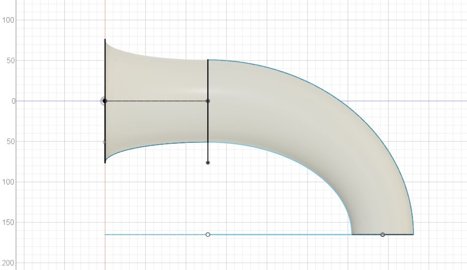
For the first design, a 6″ diameter inlet and a 3″ diameter outlet are chosen.
Beta 1:
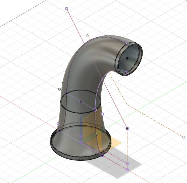
The product of the initial design effort is called Beta 1 and the profile view is shown below:
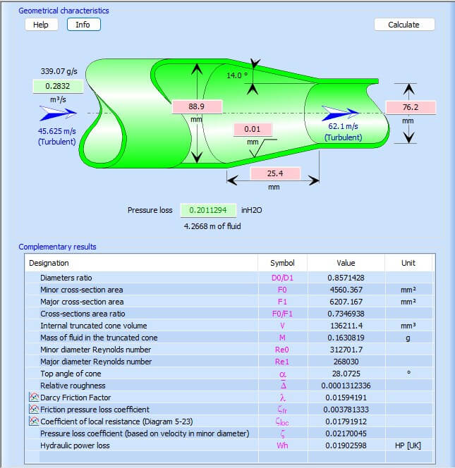
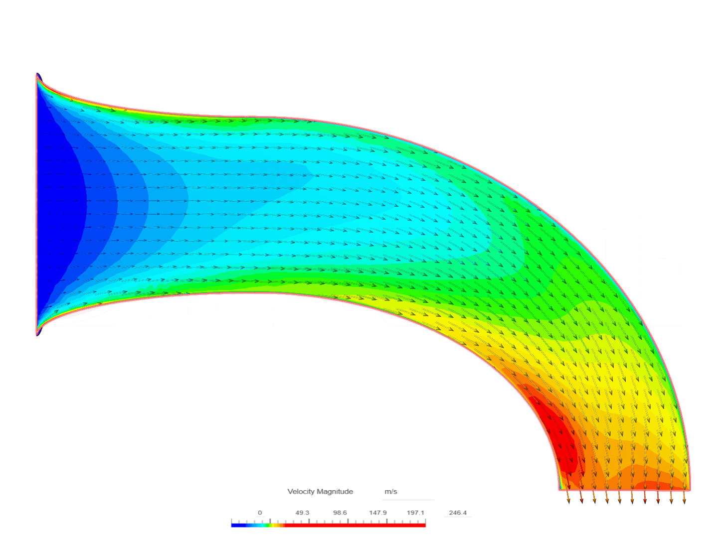
A basic analysis of the flow velocity along the intake is shown in the computational fluid dynamics rendering below:
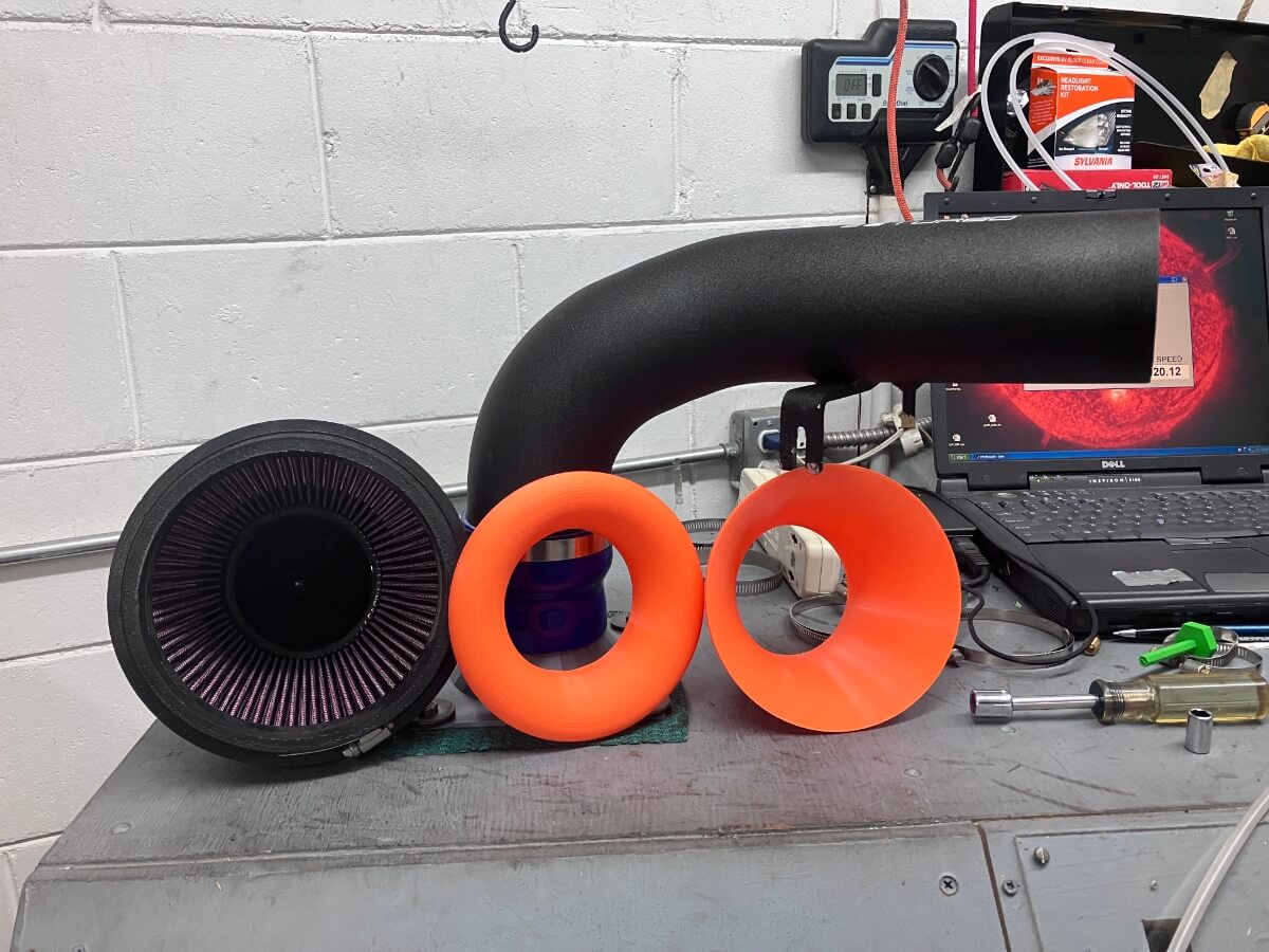
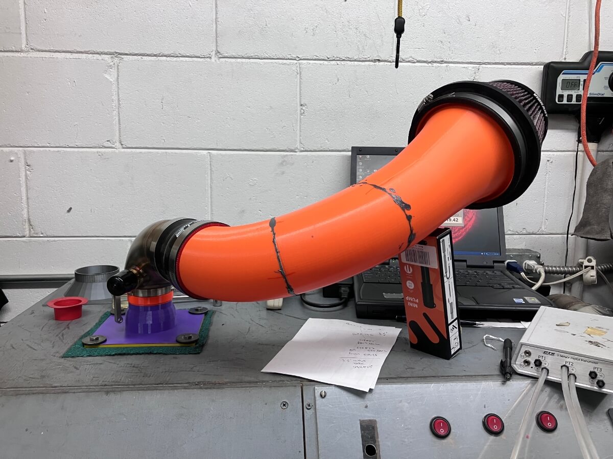
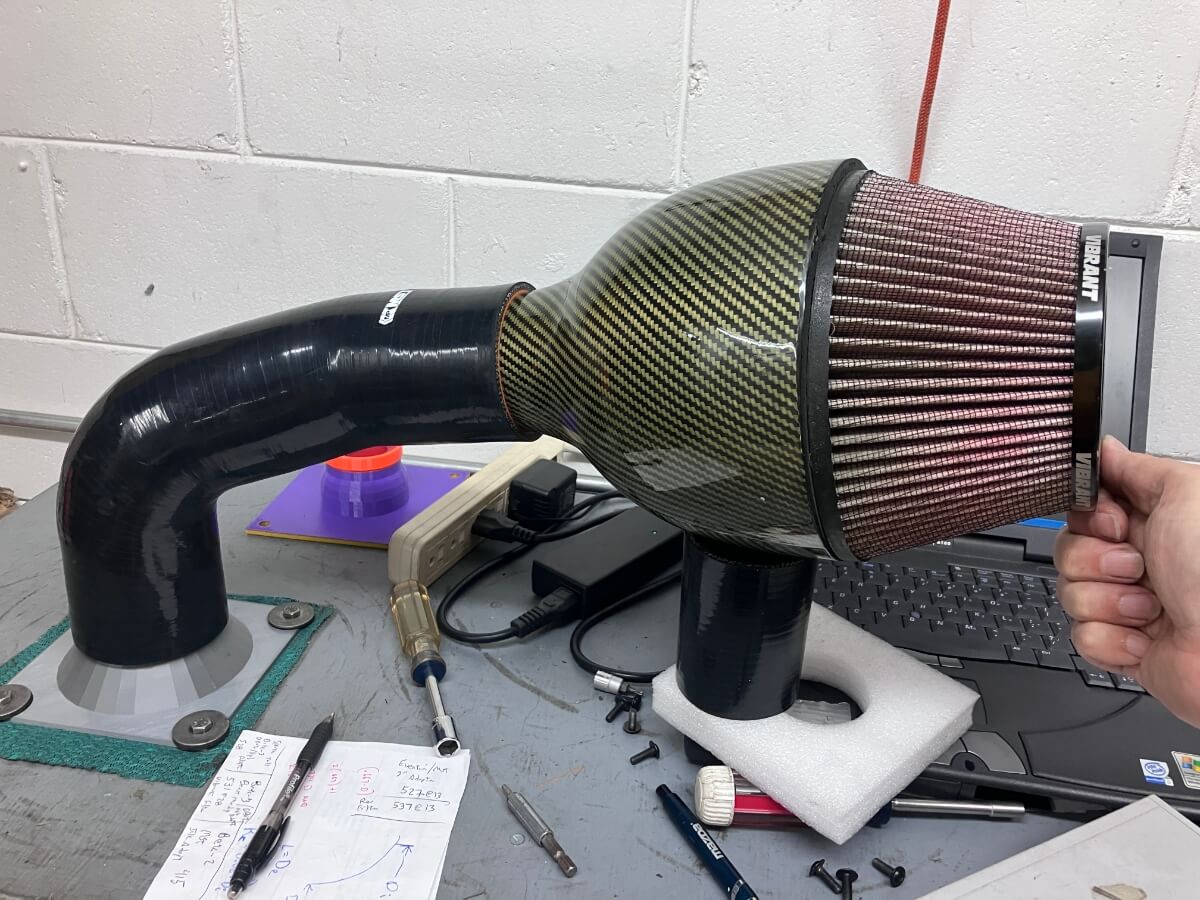
The Beta-1 prototype model was then printed and flow-tested using a Vibrant cone air filter:
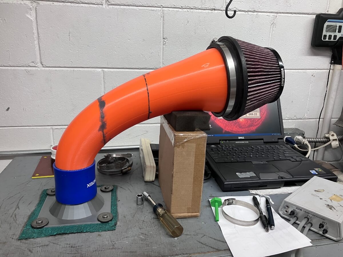
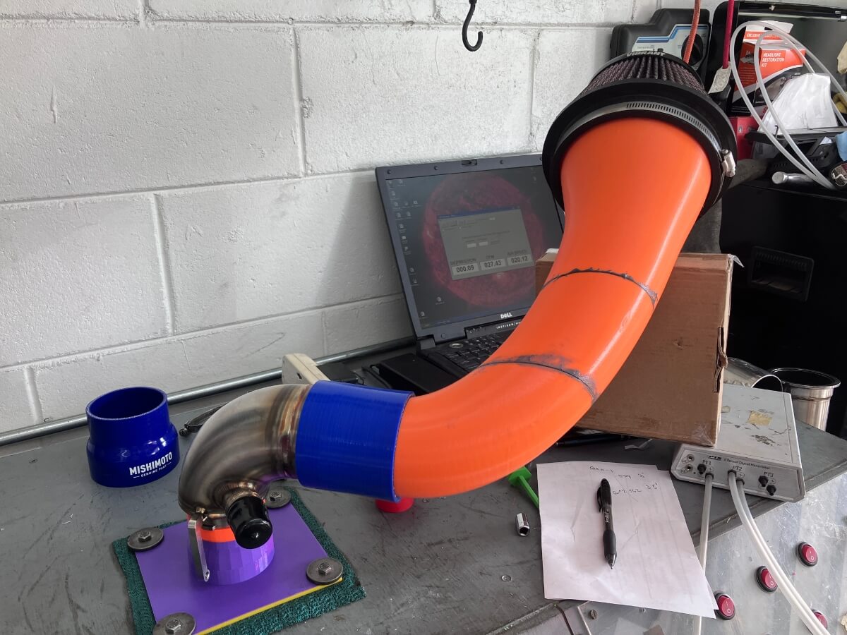
It was also tested with an inlet elbow to see how the airflow rate compares with other commercial intakes that I have tested:
Results:
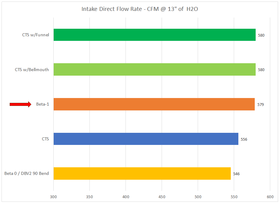
The flow rate through the Beta-1 intake without the inlet elbow is 579 CFM @ 13″ of H2O.
This is on par with the flow rate measured using the CTS intake and the prototype adapters for a Vibrant cone filter.
The flow rate with the DBV2 TIP attached and the Hybrid turbo adapter was similar to what was measured from the CTS intake. (No chart is shown for this result.)
Conclusions:
The Beta-1 intake design was successful at increasing the airflow rate compared to the CTS intake, configured as delivered from CTS Turbo, by approximately 4%, or 23 CFM @ 13″ of H2O.
The Beta-1 design did not improve upon the CTS intake when the inlet to the intake pipe was modified with a larger bellmouth and a Vibrant air filter was attached. In this test, the Beta-1 equaled the performance of the modified CTS intake.
Looking ahead, the outlet of the Beta-1 being 3″ compared to the CTS intake 3.5″ outlet is likely decreasing the maximum airflow rate of the Beta-1 design. In the Beta-2 design, I intend to enlarge the pipe outlet to 3.5″
Excellent work. Looking forward to see how you can optimize airflow.
Thanks!