
Background:
This post continues a series where design considerations around an intake I am developing are discussed.
An often-cited property of an intake is a “ram air” effect. This refers to ambient air being scooped up as the car moves forward and the air density increasing as the fast-moving air slows down and the air pressure rises (Bernouilli’s Principle).
Most of the information I could find on the subject dealt with purpose-built scoops extending beyond the vehicle used in racing applications where speeds were in the 150 to 250 mph range.
I’ve made several prior posts on the subject of ram air (Searching for Ram Air section) and did not measure any significant effect with my GTI.
Still, for the Mk7 several vendors claim their intakes take advantage of a “ram air” effect, so considering a design solution that will enable my MGM7 intake to take advantage of this effect is something to research.
Test Setup:
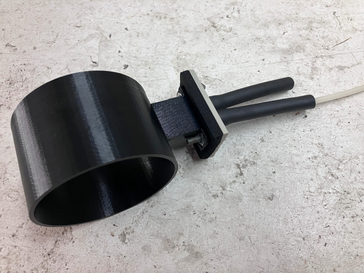
To find out how much ram air is available on the Mk7 my approach is to measure the airflow velocity through the intake. This is accomplished using an Averaging Flow Sensor (AFS) and a differential pressure gauge.
The AFS has an opening facing into the air stream and another on the back, out of the direct air stream.
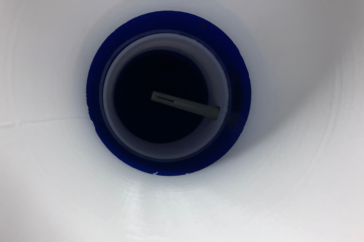
The forward opening measures Total Air Pressure and the rear opening measures Static Pressure. The difference between the two is the Dynamic / Velocity pressure.
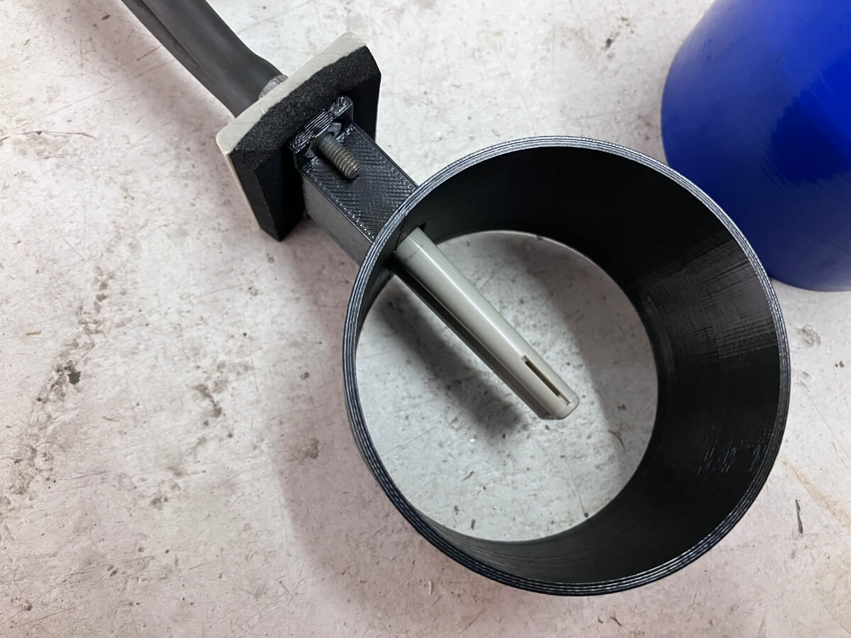
As shown above, an enclosure was made to hold the AFS so that the openings are in the middle of a tube of similar diameter to the intake accordion hose.
A check was performed to see that the AFS registers the change in air pressure with a change in airflow velocity.
After that, a series of measurements are made at different flow rates to correlate the Velocity Pressure with an airflow speed. Through the use of a pitot-static tube, the airflow velocity inside the AFS holding tube can be measured on the flow bench.
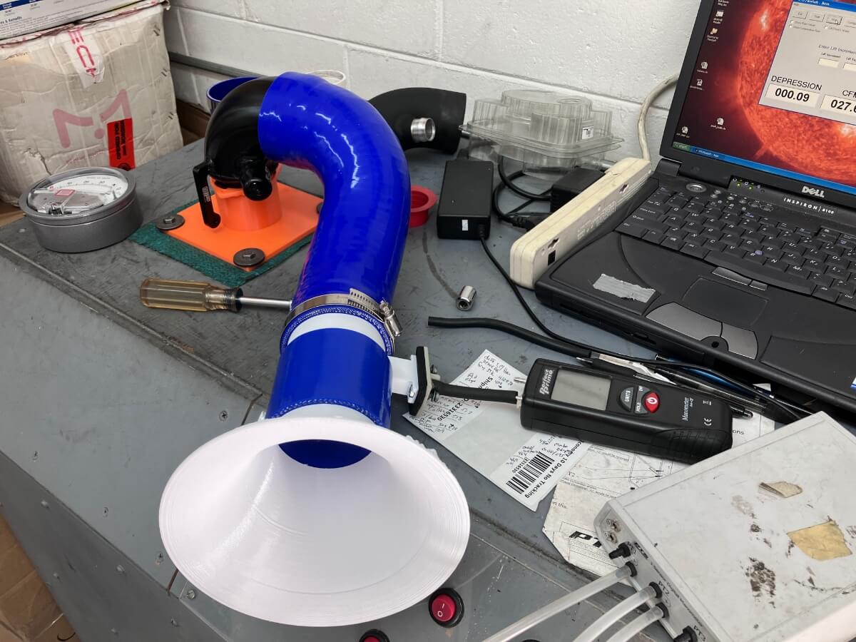
With the correlation values determined a second AFS holder is made, this one using a material that does not deform when subjected to the high air temperature inside the GTI engine compartment.
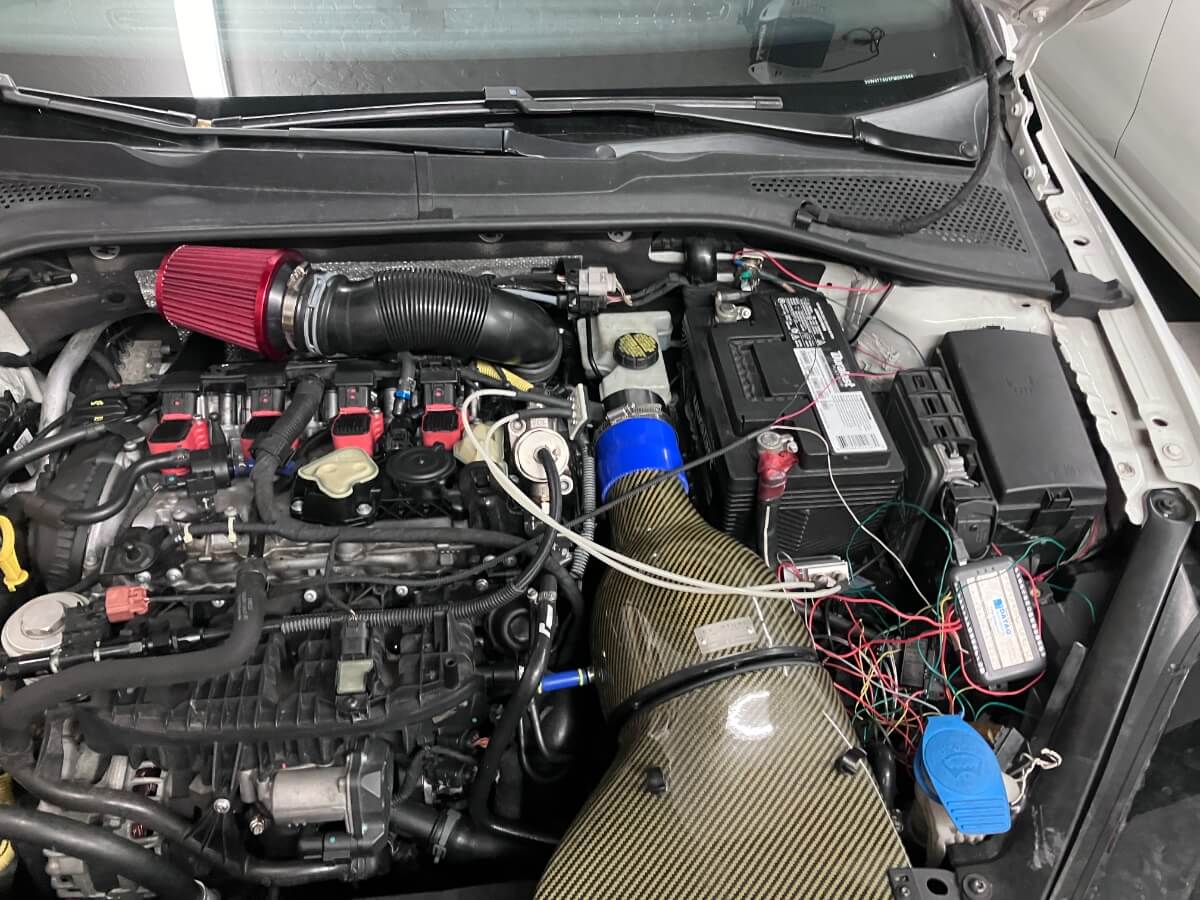
The AFS holder is to be attached to the outlet of an air intake using a silicone coupler, shown below:
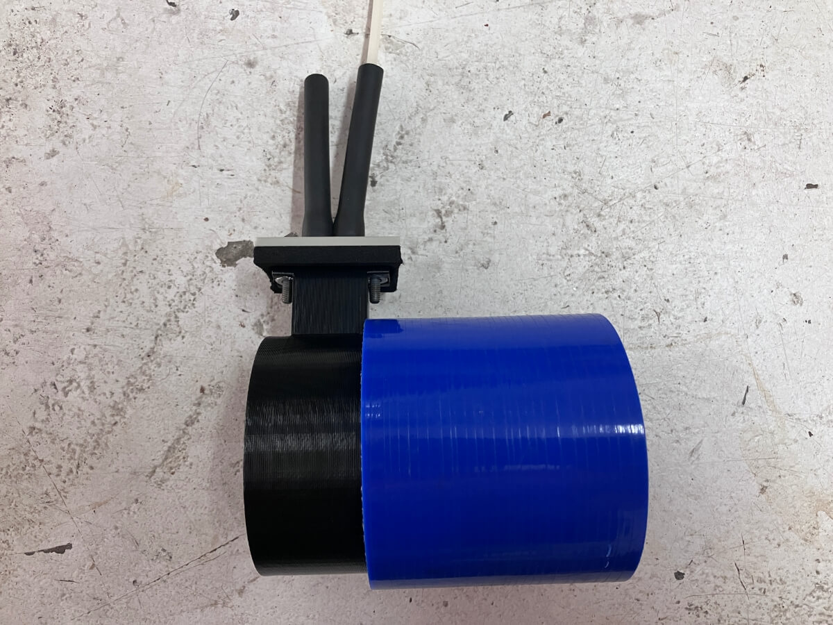
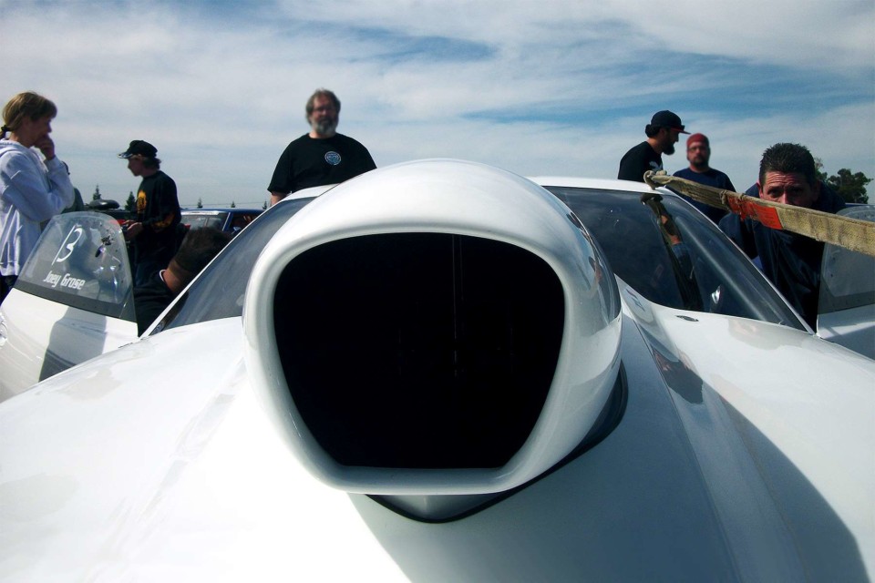
In this way, air should enter the intake on the right side of the picture where the red intake scoop is located after it passes through the GTI grill.
If the advertising claims are accurate, the onrushing air will pass through the intake (carbon fiber components in the above picture), then through the blue silicone coupler, and finally through the AFS holder and past the AFS pressure ports into the engine compartment.
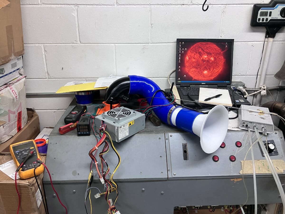
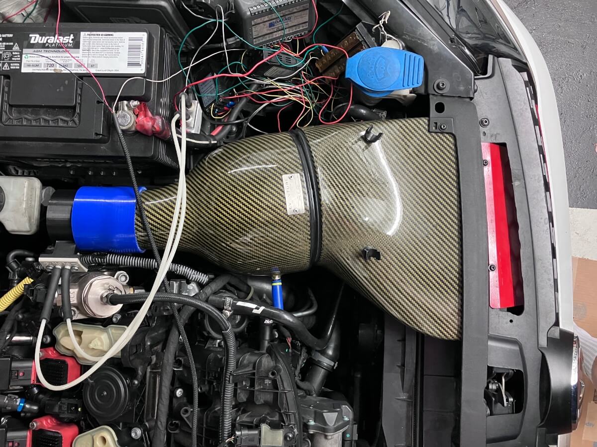
The full setup is shown below. The stock accordion hose remains attached to the turbo inlet elbow and is rotated to the side so that a small air filter can be attached.
The GTI is then driven on the street at different speeds, up to a maximum of 60 mph, to find out how the airflow through the intake varies with the vehicle’s speed.
Ram Air Test Results:
The chart below shows the Vehicle Speed over time and the Ram Air pressure (y-axis) along with the correlated Ram Air Speed (secondary y-axis).
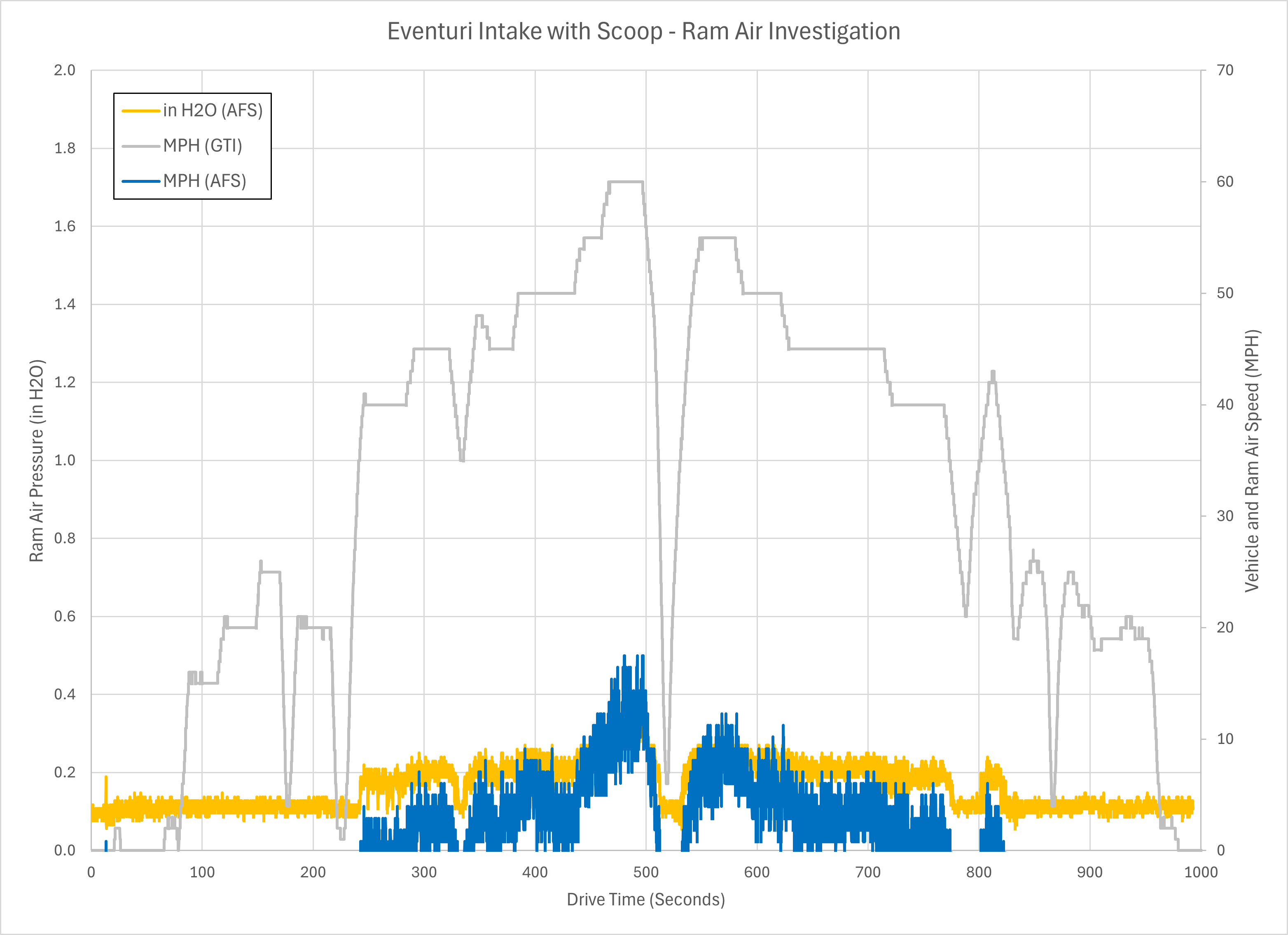
At the maximum vehicle speed of 60 mph, the Velocity pressure reaches 0.4 inches of H2O.
How much pressure is 0.4 inches of H2O in psi you ask, it is slightly more than one hundredth (0.01) of a psi.
When the vehicle is traveling 60 mph, the maximum airflow speed through the intake is just over 15 mph.
For some additional perspective on how much ram air advantage the intake might generate, in the chart below the y-axis is rescaled to a maximum of 28″ of H2O. This is the test pressure that I usually flow test intakes at. The flow rate through a typical aftermarket intake at 28″ H2O is about what an IS20 turbo takes in at 17 psi of boost and 5000 RPM of engine speed.
If the pressure drop through the intake reaches the top of the y-axis, the orange line below can be subtracted away as the “ram air” gain.
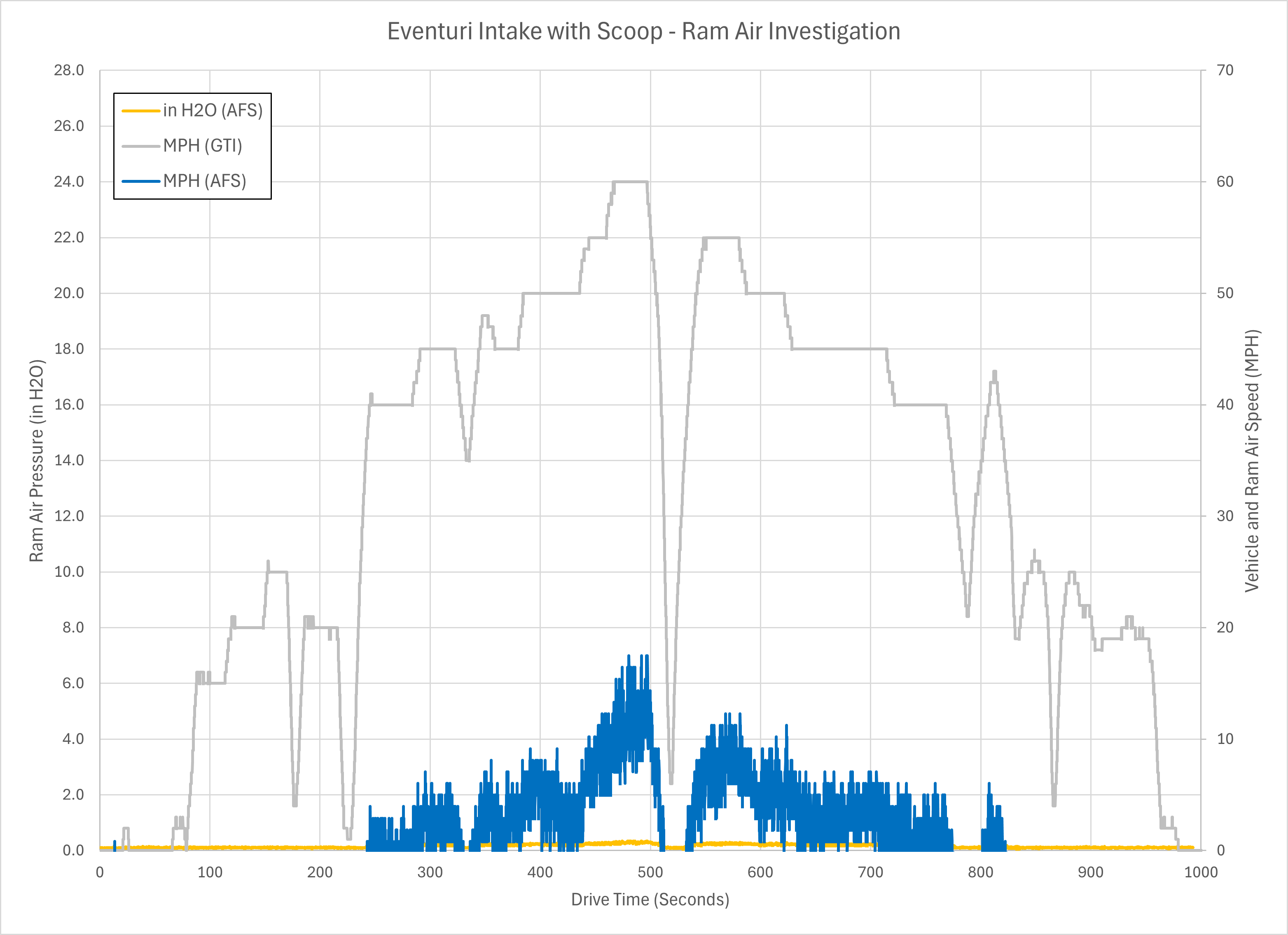
From the perspective of the turbocharger, if it is working to overcome 28″ of H2O resistance, the ram air effect lowers that to 27.6″ of H2O, at 60 mph. Or put another way from 1.0 psi of resistance to 0.99 psi of resistance.
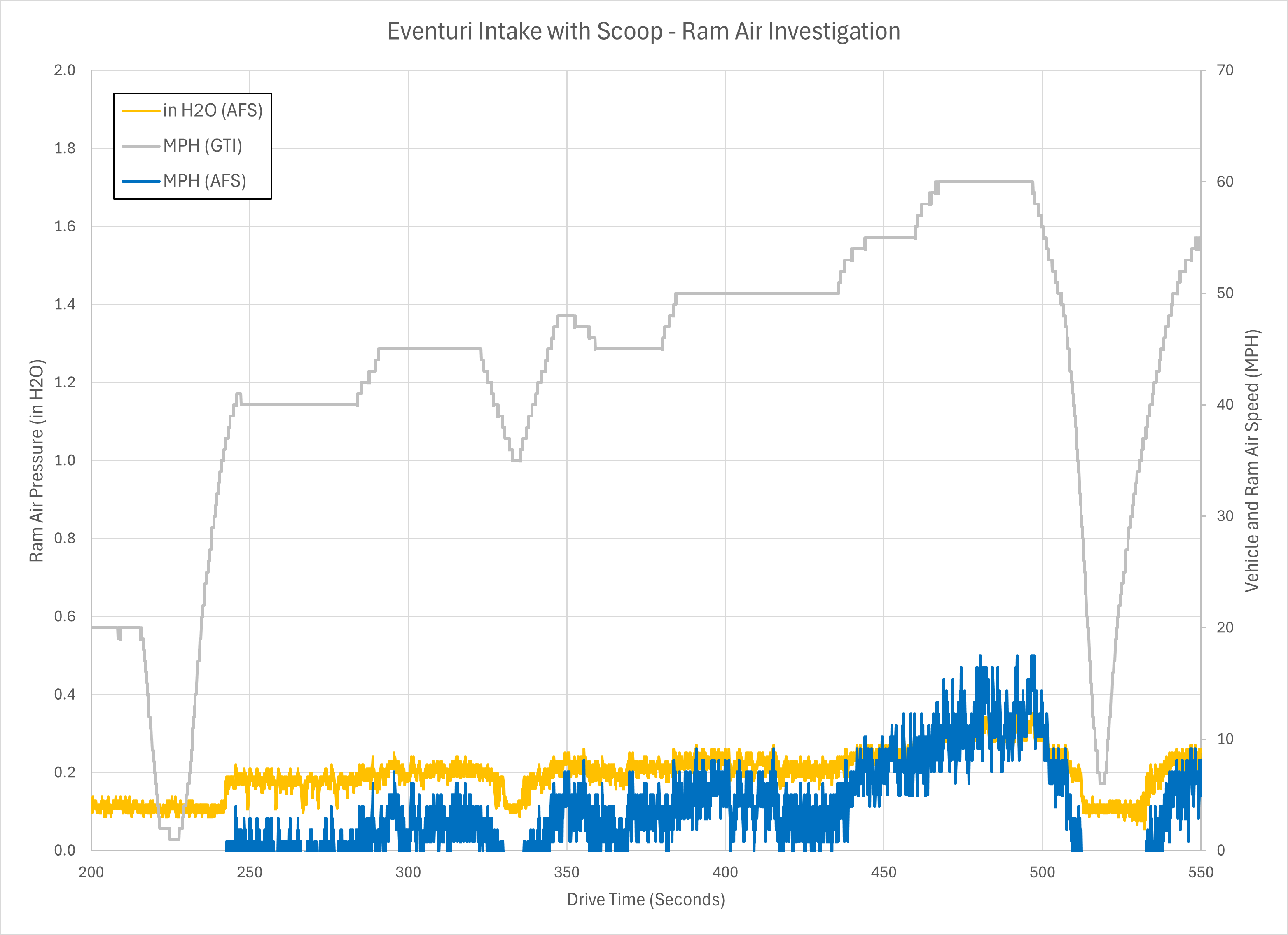
In the next chart, a close-up is shown of the range where vehicle speed reaches the 60 mph maximum.
Conclusions:
An averaging flow sensor (AFS) and differential pressure gauge were used to measure the airflow velocity through a closed Mk7 intake while the vehicle traveled at various speeds on the road.
At a vehicle speed of 60 mph, the airflow speed through the intake was estimated to be slightly more than 15 mph, based on the velocity pressure measurement of 0.4 inches of H2O at the AFS.
Relative to the pressure loss caused by a typical aftermarket intake the “ram air” effect makes a negligible difference (~1.4% decrease) in the pressure at the compressor inlet.
This test was of a single intake. This effect may be found in all intakes, making the claims about “ram air” benefits with specific intakes a moot point.