
Early turbocharger inlet elbow testing focused on evaluating the volume of airflow that each elbow could support.
The next phase of the evaluation will be focused on trying to assess how uniform the exit velocity from the elbow is.
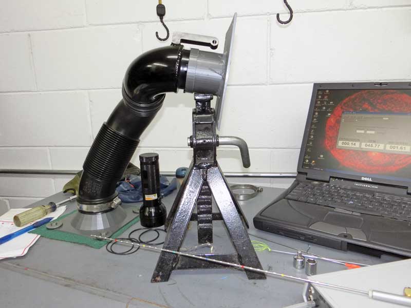
The Setup:
To be able to measure the airflow exiting from the turbo elbow the flowbench needed to be reconfigured to exhaust air. By blowing air out a pitot probe can be used to take readings at chosen locations across the elbow outlet. This change also required making a new flowbench adapter so that the stock accordion hose could connect to the bench, simulating attachment to the airbox.
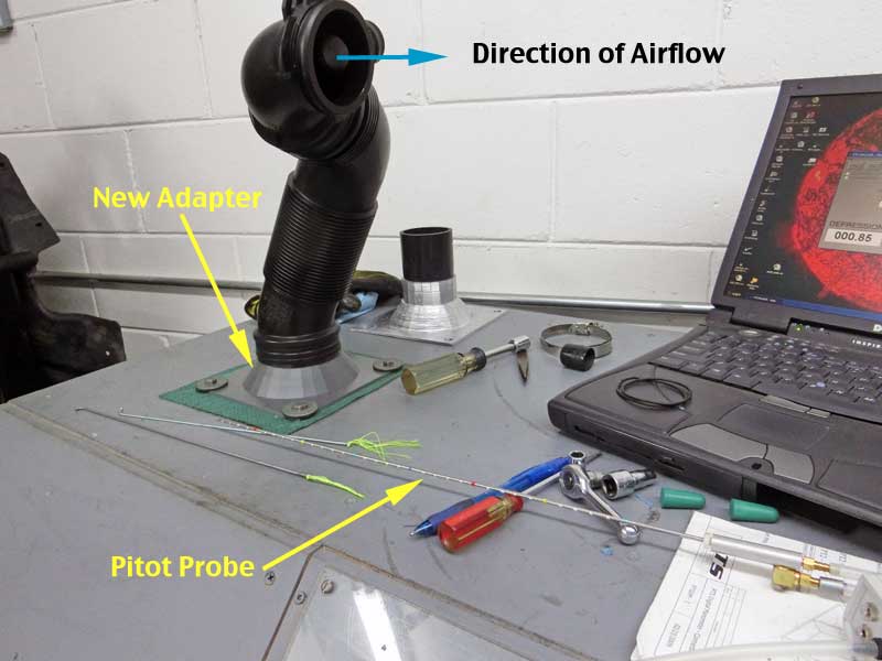
The adapter that was used to simulate the IS20/IS38 compressor housing was fitted to each inlet elbow to better simulate the airflow conditions at the compressor inducer.
The Test:
The flowbench was set to generate a 10″ of H20 pressure drop across the intake components which resulted in an air flow rate around 200 CFM.
Sampling of the air velocity was done at 9 points within the elbow outlet. The diagram below shows the approximate location of the sample points.

The number in the sector corresponds to the approximate number of degrees of where the reading was made. A reading was also made at the center of the outlet.
The pitot probe was moved to each sector and held steady while the air velocity was monitored. Turbulence in the exhaust flow caused the readings to fluctuate so that an eyeball average was taken about the approximate center of the range over which the airflow varied.
The Results:
For the first round of testing the following products were measured:
- Stock GTI
- APR
- FrankenTurbo/Burger Motorsport
- Unitronic
The series of nine readings were made two times for each elbow and the measurements were averaged. Due to slight variances in exit velocity between products the center velocity was used as a baseline value for each elbow and the perimeter measurements were evaluated as a percentage of change from the baseline.
The results are shown in the chart below:

Conclusions:
From this first test two findings are most notable. First is that the presence of the PCV port has a significant affect on the airflow velocity in that region of the outlet. The port is in the 90 degree to 180 degree quadrant and there is a notable decrease in airflow velocity for all of the products within that range.
The other notable result is that outside of the region where the PCV port is located all of the products performed very similarly, varying only by a couple of percent in most cases. Considering the “eyeball average” of the port velocity readings the results across all of the products outside of the PCV region are predominantly equivalent.