Concluding the look at how uniform the airflow is when exiting the turbo inlet elbow. In Part I explained the test setup, in this post I’m just going to present the remainder of the results.
Here’s the Leyo-Motorsport inlet elbow being evaluated:

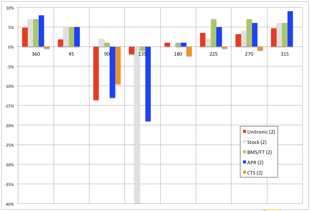
The velocity variance chart below includes one more of the inlet elbows, the CTS elbow, but I left the others from the test off this chart because the chart will get very busy and hard to read with the data from all of the inlet elbows on it.
Other than giving a general idea of what is going on at locations around the elbow outlet, the chart doesn’t convey much clear information. The most useful aspect of this chart is that it shows how across the board for these elbows the area down stream from the PCV port is an area of significant deviation in airflow velocity.

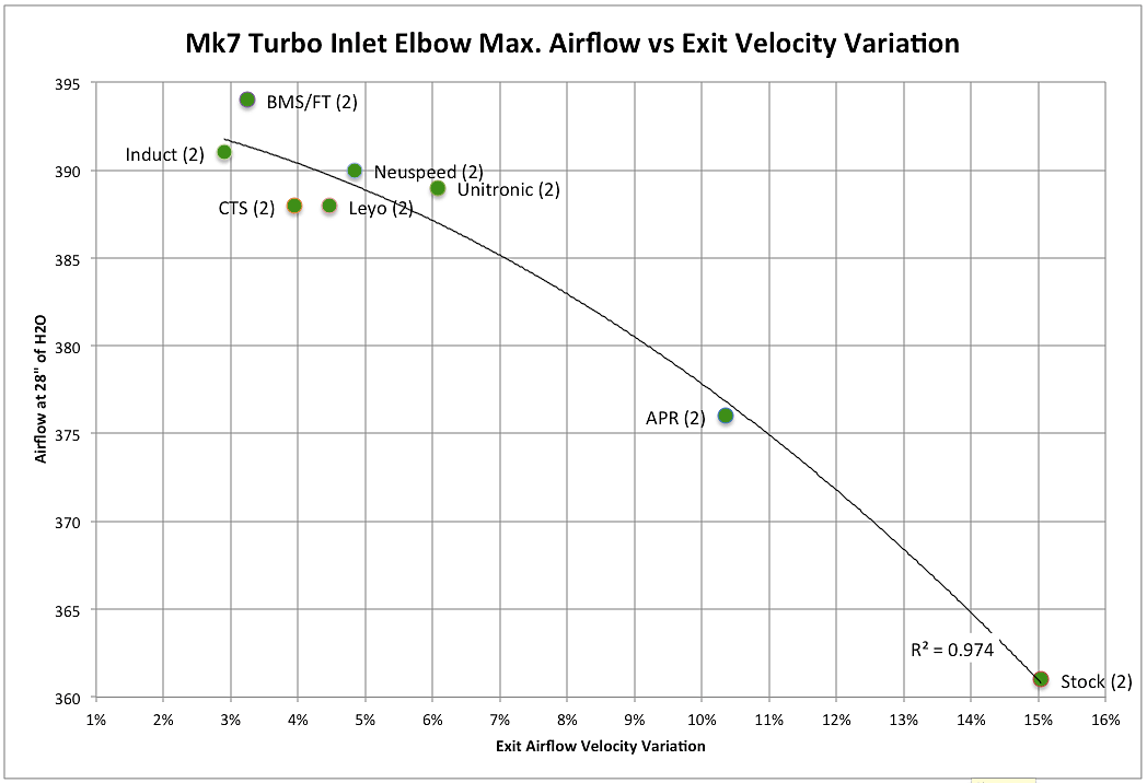
The chart below highlights how uniform exit air velocity from the elbow and maximum airflow through the elbow are highly correlated.

As the uniformity of airflow velocity breaks down, shown as an increase in percentage (%) on the x-axis, the maximum airflow through the inlet elbow decreases. This is not an unexpected result, but is an interesting look into another aspect of the design of these products that contributes to maximum airflow capacity.
It should be noted that the range of the vertical axis where airflow is reported is quite narrow. The products bunched together at the upper left quadrant of the chart are all performing very similarly. Only the APR and stock elbows show a clear break from the grouping.
