
Table of Contents
Background:
During my fact-checking of transparency in the aftermarket parts industry – an industry that supports the hobby many of us enjoy, I asked about claims that Equilibrium Tuning INC. has for a product they sell.
When they didn’t reply I decided to make a post about these unsubstantiated claims. This led to a response from their owner, Ed Susman, that failed to address the matter and changed topics to others that he also failed to provide evidence in support of.

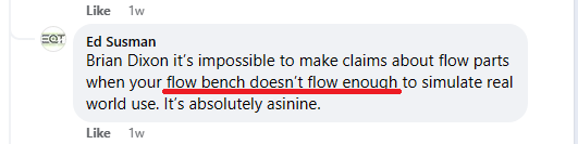
Ed commented on several unrelated topics concerning me, including a piece of equipment I use for measuring airflow; a PTS flow bench.

The comments about the flow bench had no connection with EQT’s advertising claims, but they do present an opportunity to assess if Ed Susman demonstrates having knowledge about flow benches.
Analysis:
To help with this assessment the scientific method will be applied with assistance from Olga.

1. Ask a question
Ed’s comments caused me to wonder, is Ed Susman knowledgeable about flow benches?
2. Research your topic
Ed Susman:
Ed Susman is the owner of Equilibrium Tuning INC., an automotive parts and service business. Ed’s website states that he has over 12 years of experience in software engineering.
Ed’s website states he does tuning. There is no indication that the business operates a flow bench.

Flow benches:
Flow benches of various designs have been relied on for supporting automotive research and development for over 75 years. The device measures the resistance of a test piece (intake, intercooler, downpipe, etc.) to the flow of air.
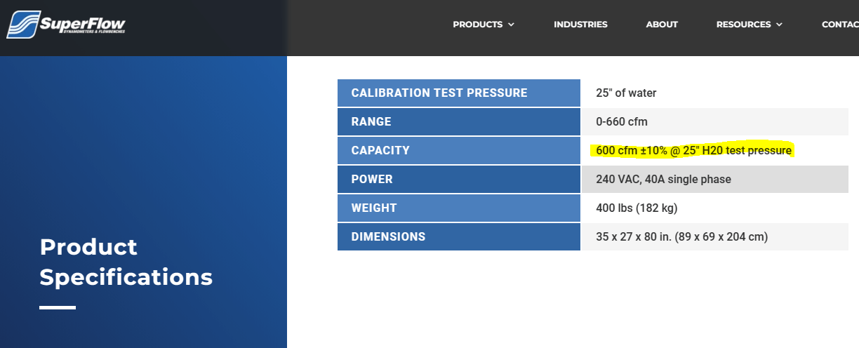
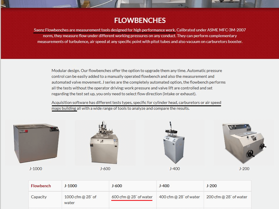
The PTS flow bench that I use, with a capacity of 600 CFM @ 28″ of H2O, is an internal orifice design that is comparable in design and performance to commercial products sold by SuperFlow with their SF-750 model (600 CFM @ 25″ of H2O), and Saenz with their J-600 model (600 CFM @ 28″ of H2O). (More on these below).
3. State your hypothesis
Ed Susman lacks a rudimentary understanding of flow bench test pressure and flow rate requirements.
4. Conduct your experiment
The experiment, in this case, involves collecting and analyzing information (verification by analysis) from different sources on the capacities of flow benches that are used for flow testing automotive parts, to gauge what these sources show to be adequate.
5. Analyze your data
Source: EQT
The most obvious source for information is Equilibrium Tuning – they are the originator of the claims.
I contacted Equilibrium Tuning on August 27, 2023, seeking evidence the company could supply to support Ed Susman’s claims.
This email is shown below:

The company failed to respond.
This is a dramatic change from several months ago when Ed Susman was very outspoken on social media, stating to other enthusiasts that the flow bench that I use is inadequate.


It seems the “experts” at EQT are learning that backing up an accusation isn’t as easy as making one.
Because Ed Susman presented no evidence when making his claims, nor would he upon request for this analysis, there is no evidence that supports Ed Susman’s claim that a flow bench that flows 600 CFM @ 28″ of H2O “is inadequate to test automotive flow parts“.
Source: Industry & Established
The following sections will present evidence showing that 600 CFM @ 28″ of H2O is sufficient to flow test automotive parts.
What does Superflow have to say on the topic of flow benches? Who is SuperFlow?
Here is information about the company that has been in the business of supplying automotive-related organizations with flow benches for 50 years.

Here’s information on one of the flow bench models that Superflow sells, the model SF-750. This bench supports a pressure and flow rate that is similar to the PTS flow bench.

Another well-known name in commercial flow benches is Saenz. Saenz also serves automotive-related industries and offers a model, the J-600, with a similar performance to my PTS flow bench.
Industry Analysis:
Returning to the claims made by Ed Susman, that a flow rate of 600 CFM @ 25″ of H2O (Superflow SF-750) or 600 CFM @ 28″ of H2O (Saenz J-600), is “inadequate to test automotive flow parts“.
On the one hand, there is Ed Susman, software tuner and owner of Equilibrium Tuning baselessly claiming the PTS, Super SF-750, and Saenz J-600 flow benches are inadequate for testing automotive parts.
On the other hand, there are two international companies that have been in the business of making flow benches to support the testing of automotive parts for about 50 years, selling flow benches that Ed Susman claims are “inadequate“.
If Ed Susman were correct, it would mean that Superflow and Saenz failed to understand the level of performance needed from their SF-750 and J-600 benches for their customers.
Additionally, for Ed Susman to be correct, it also means the automotive performance shops that have purchased the Superflow SF-750 or Saenz J-600 flow benches over the years, at a cost of around $12,000-$15,000, were unaware they were purchasing an “inadequate” piece of equipment.
It is illogical to conclude that these two companies failed to understand what level of performance was required from the products they sell to satisfy their customers.
It is also illogical to conclude their customers failed to understand what level of performance they require from a flow bench.
Finally, it is illogical to conclude that a failure in understanding by both sellers and buyers of commercial flow benches has been going on for decades.
Established test standards:
In this section, guidelines for testing using a flow bench are reviewed.
To begin, as SuperFlow describes in the Tech Corner section of their website;
The first thing you learn in flow testing is that you must ask (or qualify) at what test pressure the flow numbers were recorded.
SuperFlow
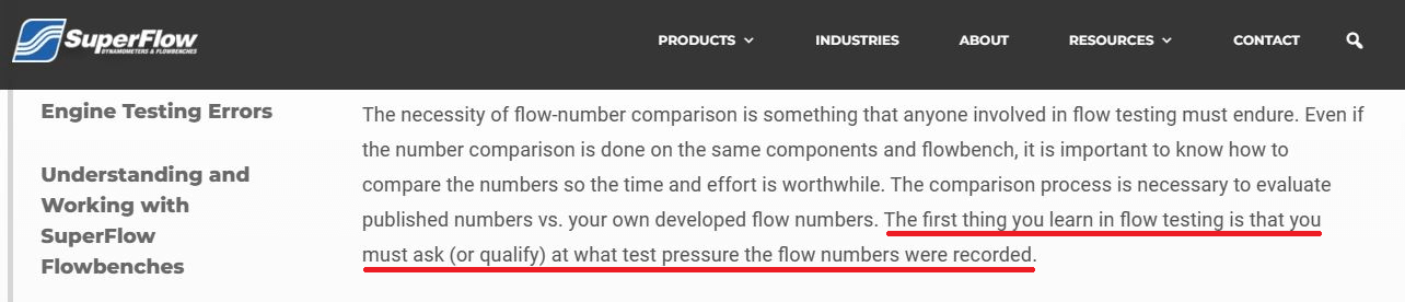
Tellingly, all of Ed Susman’s accusations concerned flow rate only, Ed never mentioned the test pressure. This leads to the logical conclusion that, in SuperFlow’s words, Ed Susman doesn’t know “the first thing you learn in flow testing”.
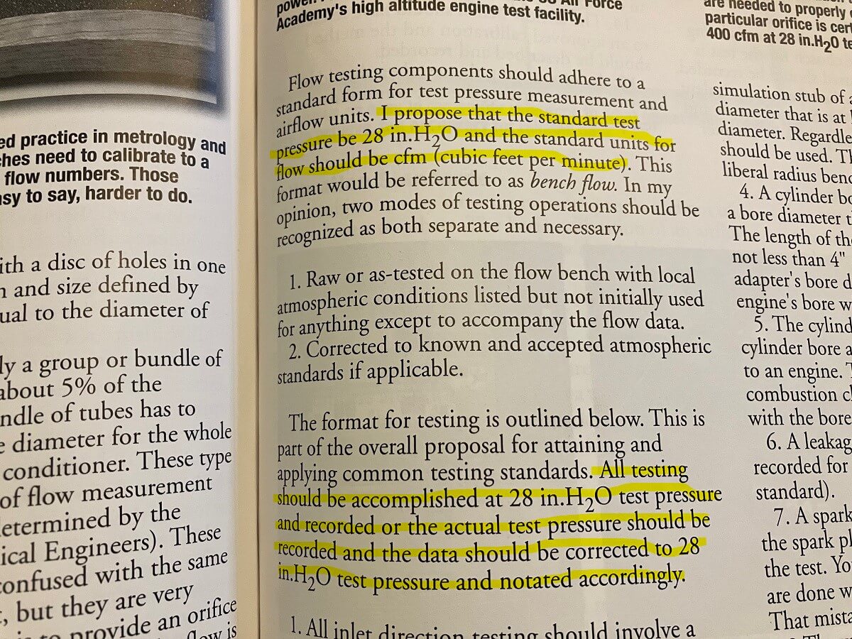
On the matter of test pressure, Harold Bettes, who passed away in 2021, literally wrote the book on airflow (Engine Airflow – by Harold Bettes).


Harold suggests a test pressure of 28″ of H2O be adopted as a standard for testing. This is the pressure I predominantly test at.
What about Ed Susman’s statements about the PTS “flow rate” being “inadequate to test automotive flow parts“?
The flow rate to test with is not addressed by Harold Bettes or Superflow, because the test pressure is what matters.
Mathematical modeling: Irrelevant, but why not:
After going over the fact that how much airflow a flow bench supplies is not a primary concern in obtaining useful information, I will go through an exercise to mathematically prove that Ed Susman’s claims are false.
Using information about the Mk7 engine size (2L), operating speed, volumetric efficiency, and boost pressure, and assuming standard atmospheric conditions, it is possible to calculate the volumetric airflow rate (CFM) through the intake and exhaust of the GTI.

Note: These calculations can also be performed using an online tool like Borg-Warner’s Matchbot, but the spreadsheet facilitates looking at a greater number of operating points simultaneously.
Highlighted in the chart above are the general maximum operating boost pressures near the engine redline for an IS20 and IS38 turbocharger and the corresponding airflow rate for different engine speeds.
Note: It’s not immediately evident from the table, but for these operating ranges airflow rate is more affected by engine speed than boost pressure.
With these values, it is possible to plot the engine airflow rates and compare them to the flow bench’s maximum flow rate of around 600 cubic feet per minute.

For the intake and exhaust components that cause minor pressure losses, such as the airbox, charge pipes, downpipe, and exhaust pipes, 600 CFM exceeds the operating flow rate of an IS20-equipped 2L engine near the redline and is approximately equal to the operating flow rate of an IS38 equipped 2L engine.
Thus, Ed Susman’s claim that an airflow rate of 600 CFM @ 28″ of H2O is inadequate to flow test automotive parts is proven to be false.
6. Draw your conclusion:
Ed Susman baselessly claimed that flow benches capable of flowing 600 CFM @ 28″/25″ of H2O, for example, the SuperFlow SF-750, Jaenz J-600, and PTS (8-motor), are “inadequate to test automotive flow parts“.
Ed Suman failed to provide evidence to support his claims at the time he made them. Ed also failed to provide evidence to support his claims when requested.
Evidence was presented showing international manufacturers of flow benches supply automotive-related organizations with flow benches that flow 600 CFM @ 25″/28″ of H2O.
Evidence was presented that authorities in the field of flow bench testing recommend a test pressure of 28″ of H2O for testing and do not suggest standard flow rates for testing.
Calculations were presented showing that a flow rate of 600 CFM, which the PTS flow bench is capable of, exceeds the flow rate of the IS20-equipped Mk7 GTI at the engine redline.

All evidence related to the question: “Is Ed Susman knowledgeable about flow benches?” points to a conclusion of no, Ed Susman is not knowledgeable about flow benches.
All available evidence also demonstrates that Ed Susman’s claims are false.
Implications:
The evidence showing that EQT owner Ed Susman made false statements about my flow bench has several significant implications.
Ed Susman’s false statements about the flow bench were in response to my review of EQT’s advertisement that lacked substantiation. The effort by Ed to mislead consumers about the pertinent issue suggests that addressing the unsubstantiated claims was a matter that Ed vigorously wanted to avoid.
Ed Susman repeatedly made a false claim to consumers that the flow bench I use is inadequate, baselessly trying to discredit me, the work I have done, and the information I have presented.
Ed’s false claims have been believed by some consumers (see my post about Diego the YouTuber) which has led to decreased confidence in flow bench-derived test results. This erosion of confidence in test-derived information from a measurement tool that has been a cornerstone of automotive product development for decades is a disservice to consumers.
The failure of EQT to address their claims about the flow bench is inconsistent with an organization that has knowledge on a subject.
Taken together, the unsubstantiated advertising claims, false accusations, attempts to discredit my work, misleading consumers, and failure to provide evidence raise questions about the business ethics of personnel at Equilibrium Tuning INC.
The matter of business ethics will be further investigated in future posts reviewing EQT.
Bet you 20$ ed @ eqt won’t ever address this post and will pretend they have never read it
Surely, Mr Susman would be considering some form of defamation against you if he had any evidence to back up his ‘claims’ but I suppose he can’t because he doesn’t.
People like Mr Susman, rely on the tool (and tools) that is social media, used by many other misinformed, uneducated people to disseminate information based on ‘their opinion’ because they lack the ability to have any form of intelligent discussion. If you disagree you are wrong, irrespective of what you may be able to show them or prove, because they don’t have the ability to carry out a rational argument you have to be wrong because they are always right. Welcome to 1984.
Back when I reviewed their advertisement they made the defamation threat, which I presented in this post. Ed was pulling a misdirection back then too. My point was that their claim wasn’t being substantiated, and instead of rebutting that point, he asked for irrelevant information about me.
I wholeheartedly agree that they are overly reliant on opinion-based conclusions.
I wonder how many customers are actually fooled by EQTs lies, compared to those – like me – who have lost all respect and confidence for the folks at EQT over the way they conduct themselves regarding this situation. Honestly, if they aren’t already, i feel the BBB and/or FTC should be involved. EQT is very close to, if not actively, committing libel against you and the companies that manufacture the test equipment. At least that’s how it looks from my uneducated opinion
My guess is the majority.
They are checking all of the boxes for making libelous statements. The false claims about me are just a symptom of a widespread problem consumers have with information coming from EQT.
The post I made today shows another example of EQT making deceptive statements to consumers.
Interesting information… that Ed guy sounds a little crazy.
But I see that you’re using IS20 and IS38’s as your main limit of flow. What about larger turbos like hybrids that can flow a lot more air than the OEM turbos? Many aftermarket parts are being released for those bigger turbos, so how can you accurately test those parts with your flow bench if it can’t flow more than an IS38?
Also, check out this video: https://www.youtube.com/watch?v=VUCo3REGrLE about flow benches. What’s your opinion on that?
Like I mentioned in section titled “Mathematical modeling: Irrelevant, but why not”, having a bench that flows some specific amount of CFM is not a significant consideration. The device measures resistance to airflow allowing for making relative comparisons. Think of it this way, if you stuck your hand out the car window at 45 mph and held your hand parallel to the airflow you’d feel some resistance, and if you turned you hand perpendicular to the airflow you’d feel a different amount of resistance, which would be greater, due to the increased surface area being impacted by the air. Now drive at 75 mph and repeat the process. Is the force on you hand when held parallel now going to be greater than when it is perpendicular? No. The relative effect is the same at each air speed, one configuration has more resistance than the other. That’s kind of how the flow bench functions, it allows for relative comparisons using a defined test pressure.
The video is an infomercial for the Banks iDash DataMonster. What do you think the likelihood of “Everybody” being wrong for the past 50 odd years is? OEMs, Racing programs, everybody has been wrong and only Banks figured this out? There’s nothing wrong with measuring mass flow, but many benches, like the one I use, provide a measurement that can be equated to standard atmospheric conditions so you could calculate the mass flow rate. It wouldn’t make a difference, resistance to flow is what we’re interested in knowing.
But then you are not really testing the part under the actual flow conditions it sees in real world operation. Is it possible that there are design elements of flow parts that only become a restriction at higher flow rates. If so, how can you compare such parts without reaching those flow rates?
Let’s say you have two intakes designed to flow enough air for 700hp without significant restriction. Maybe one of the intakes does not flow as well at that flow rate, creating a restriction to flow and creating a slight vacuum at that flow rate. The second intake has a better design and does not restrict flow at that rate. In this case both intakes could flow 300-400hp worth of air without creating any measurable restriction or vacuum at all, but once you start hitting higher flow rates, the differences in flow restriction start to show up. How can your flow bench show these differences in parts that are designed to flow a lot more air than your bench is flowing?
The video doesn’t seem like an infomercial and does present some interesting points. I’d like to see you address those instead of dismissing them because you claim that “Everybody” has been doing something for “the past 50 years.” Do you know exactly how all OEM’s and racing programs have been designing their parts for 50 years?
P1) I am measuring the pressure loss caused by the part using a device that measures pressure drop. I’m not aware of conditions on the car that would alter the properties of the parts such that the relative pressure loss measures would be invalidated.
An area of supersonic airflow would produce a shockwave and lead to a sudden pressure increase. I think that would be unlikely to arise in the intake since the turbo inlet is the smallest cross sectional area of the intake, and to maintain continuity there would likely be supersonic airflow at the inlet. Creating a shockwave at the compressor inlet would not be good for the compressor blades and bearings.
There’s the possibility of an inlet hose collapsing which does seem to occasionally occur. I’ve been under the impression this is a product of both the higher temperature inside the engine compartment, making silicone more pliable, combined with the vacuum inside the intake. That to me is more of a structural design concern than aerodynamic.
P2) In your hypothetical scenario, are you describing a situation where the airflow rate suddenly drops such that where one intake was flowing more than the second, the second is then flowing more than the first? This is shown with the superimposed red line on the do88 airflow chart for their MQB intake.
I can’t recall ever seeing that occur, and I think it would invalidate the Darcy-Weisbach equation if it did, at least for incompressible flow.
P3) Can you be more specific about what points you find interesting in the video that you’d like me to comment on?
I do not know exactly how OEM and Racing programs have been designing their parts, I didn’t claim that I know that. Banks claim is that “Everyone is measuring airflow WRONG” Their explanation for why is that people should be measuring Mass Airflow rate instead of Volumetric Airflow rate. Measuring Mass Airflow rate is not a new idea, it’s an alternative method, but not necessary for the purpose of determining the pressure drop across a part.
P1/2) I’m not talking about airflow suddenly dropping or any dynamic mechanism like a collapsing coupler. I’m only using intakes as an example here, but we can talk about hard pipes like downpipes, exhaust, etc.
Let’s think about an extreme example. Let’s say you’re testing two very different designs of exhausts. One is a 2″ pipe with a a muffler, the other is a straight 6″ pipe with no muffler. For this example, let’s assume that the 6″ pipe can flow something like 900CFM at a given test pressure, and the 2″ pipe will flow much less… something like 400CFM. In this case you would expect to see a clear and obvious difference between the two even if the bench can’t really flow enough air for the open 6″ pipe to show a restriction to flow. Now let’s test a 5.5″ open pipe to compare, and let’s assume this pipe flows something like 800CFM at the same test pressure. In this case, how can your 600CFM bench show the difference in restriction to flow between the 6″ and 5.5″ pipes?
P3) I’m curious how this effects testing of parts that normally see boost pressure and highly variable temperatures. Intercoolers are a good example of this. Considering that they are meant to operate at a very wide range of pressures and temperatures, it seems like a classic flow bench would only show a very small part of the overall story.
Finally, what about about parts like intakes that may see a ram air effect with varying vehicle speeds. How can a flow bench reproduce such conditions?
In the exhaust scenario, if the 6″ pipe was able to flow more than the bench maximum airflow rate and not be detected by the digital manometer, which has a resolution of 0.01 psi, there would not be a reading for that part. If the smaller pipe also was able to exceed the flow bench maximum flow rate, and also not cause more than 0.01 psi of backpressure at that flow rate, then a comparison would not be possible with the flow bench I’m using.
Changes in temperature and pressure on the car will affect the air density. The flow bench uses an internal orifice plate to measure the pressure difference across the plate (YouTube video on this) and compare that with the pressure difference across the test article. Since both the part and orifice plate are working with the same air, at the same density, the air density does not affect the reading. It’s referred to as a ratio-metric measuring device.
I also log pressure drop on the car from the turbocharger outlet to the intake manifold and the measurement correlates well with the flow bench measured values.

The flow bench measures the resistance the part causes to airflow across the part. If some part of that test article has an interaction with airflow that is affected by the vehicle body, that won’t be accounted for.

I have tried measuring the magnitude of the “ram air” effect on the GTI and it seems negligible compared to the vacuum the compressor draws air in at.
Is it possible that some aspects of the design of a flow part will only become a restriction at higher flow rates and may not be significant enough to measure at lower flow rates? I could imagine that turbulence around certain bends or design elements could be variable depending on overall airflow.
I think it would be unlikely to find a part that doesn’t cause any restriction over some range of airflow (that would violate the laws of physics) and then in another range begins to cause a restriction. The amount of resistance to airflow varies with the flow rate, the resistance is a function of the square of the velocity of the airflow.
I don’t mean no restriction at all. But wouldn’t it be possible for a part to develop a lot more turbulence at significantly higher flow rates? Such turbulence would add restriction that would only be present at those higher flow rates and not at lower flow rates. This would then break any extrapolation you might be doing from test results at lower flow rate ranges. It could also make it impossible to encounter the turbulent condition unless the flow bench was able to actually reach the necessary flow rates. Or am I way off base?
It would depend in part on how the region of turbulence is produced. Some shapes will have a set point where flow separates from the wall (boundary layer separation), which will have a constant coefficient of drag for turbulent flow, which the air flowing through the parts on the car will be in. Other shapes can have a point of separation that is not fixed, something like a sphere has this, and for that shape the coefficient of drag varies with the amount of turbulence. Although interestingly, for a sphere the drag coefficient mainly decreases with increasing Reynold’s number (ratio of inertia to viscous forces which indicates when turbulent flow exists). I think conceptually it’s within the realm of possible, but whether or not there is a real part that has the appropriate shape, and the flow conditions are appropriate to support the increase in drag coefficient, I don’t know.
Ok, so at least conceptually it’s possible that this could be a variable that is only visible at higher flow rates that may not be seen on your bench. Can we think of any other variables that may have a similar effect?
The ram air effect is an interesting one. You mentioned you tried to measure it on your GTI, but with what intake setup and at what speeds? Is it possible that the ram air effect could be significantly different with different intake design elements, especially at higher speeds like 100mph+?
If we presume the intake doesn’t change shape, and flow rate remains subsonic, the Cd (discussed already) is the one other factor that might change that could affect the drag. Density could change, but the design of an internal orifice plate flow bench takes advantage of ratiometric measurements so that it isn’t affected by variation of air density.
I tried measuring the ram air with a Eventuri intake up to about 75 mph. There is a small change in total pressure at the intake inlet, but from what I have read, on a car it needs to be going over 100 mph to get a meaningful change in preturbo air pressure. That figure of 100 mph also may not necessarily apply to the GTI, since the normal intake setup isn’t well positioned to take advantage of this.
I haven’t found there to be ram air, at least not how I think people are imagining it, air rushing into the grill and forcing its way down the intake. There seems to be slightly higher static pressure inside the grill, but I didn’t get indications there is a dynamic pressure component of the total pressure.
Any ram air effect is outside the scope of what a flow bench is meant to measure. The flow bench measures the resistance to airflow caused by a part. A ram air effect is using the vehicle body and speed to create a higher-pressure area at the intake inlet – that is outside the body of the intake. Ram air effects should be measured on the vehicle. If we want to talk ram air effects, we should cross reference tests that have been performed by other people with the measurements I’ve made to see how well the results agree.
So it does sound like there may be factors that are not being measured by your flow bench? May be a good idea to explore these factors… maybe write an article about them and add a disclaimer to your results?
Thanks for the suggestion.