Background:
Seeing an implementation of a foglight duct on the GolfMk7 forum by yakboyslim prompted me to print out a copy of the design to check the potential benefit to an intake design I am working on.
The idea of replacing the foglights with some type of duct is something I have thought about for a while, but the task of making a suitable part for this seemed to be fairly difficult and I put the project on the shelf.
Production and Install:
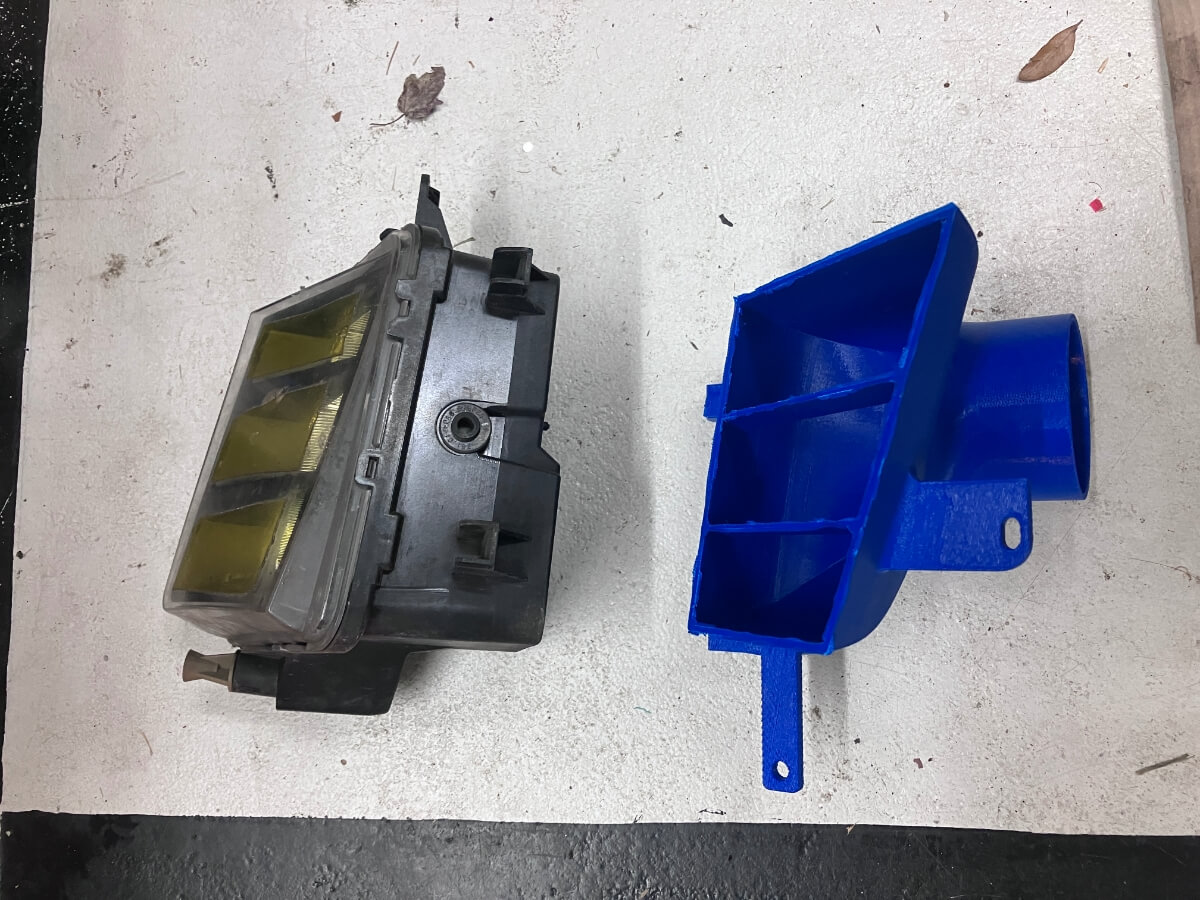
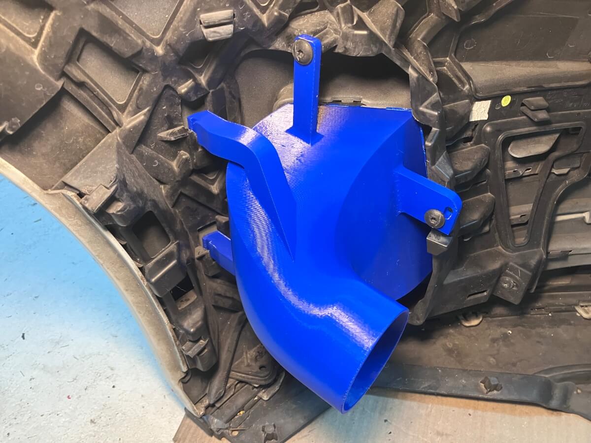
This implementation of the concept is well done and even though I missed out on the latest revision to the design, I have version 4 and version 5 is the current design, the part fits with some coaxing and the addition of a new hole to secure it in place.
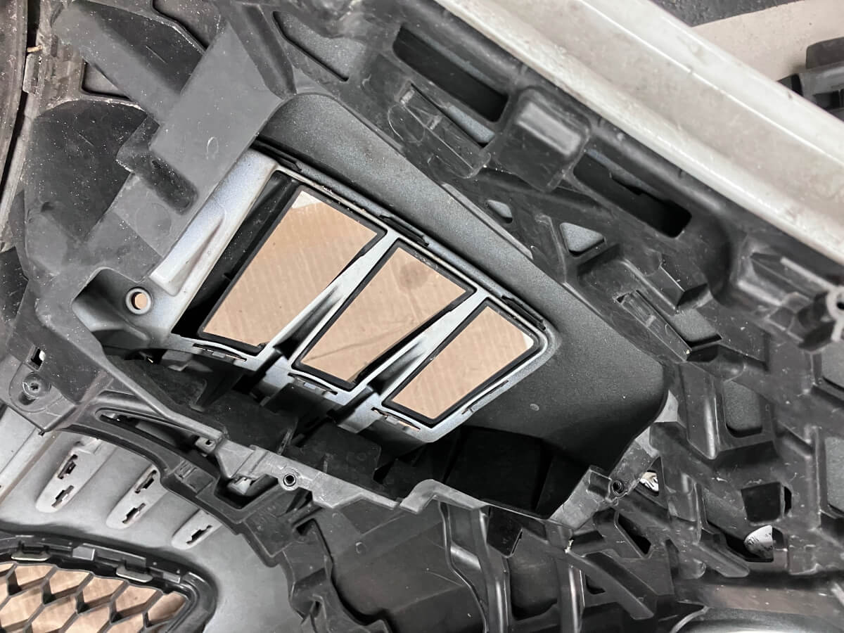
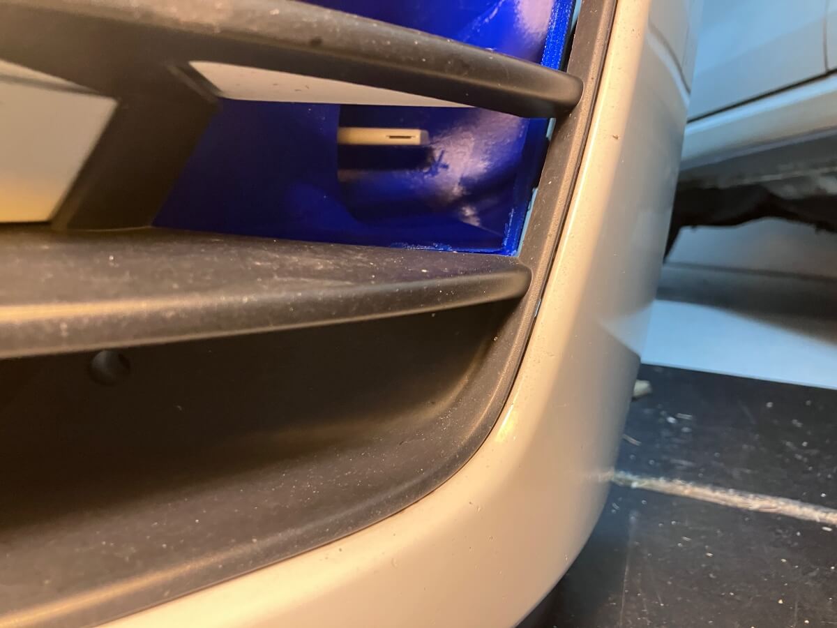
The idea of the duct is to utilize these openings in the front bumper cover to direct air to a brake cooling system or an intake.
My goal is to gauge if there is positive pressure inside the duct that can be leveraged to increase airflow to an intake. To measure the static pressure inside the duct I made a cap to seal the discharge opening and placed an averaging flow sensor (AVS) inside the duct that is configured to measure statice pressure.
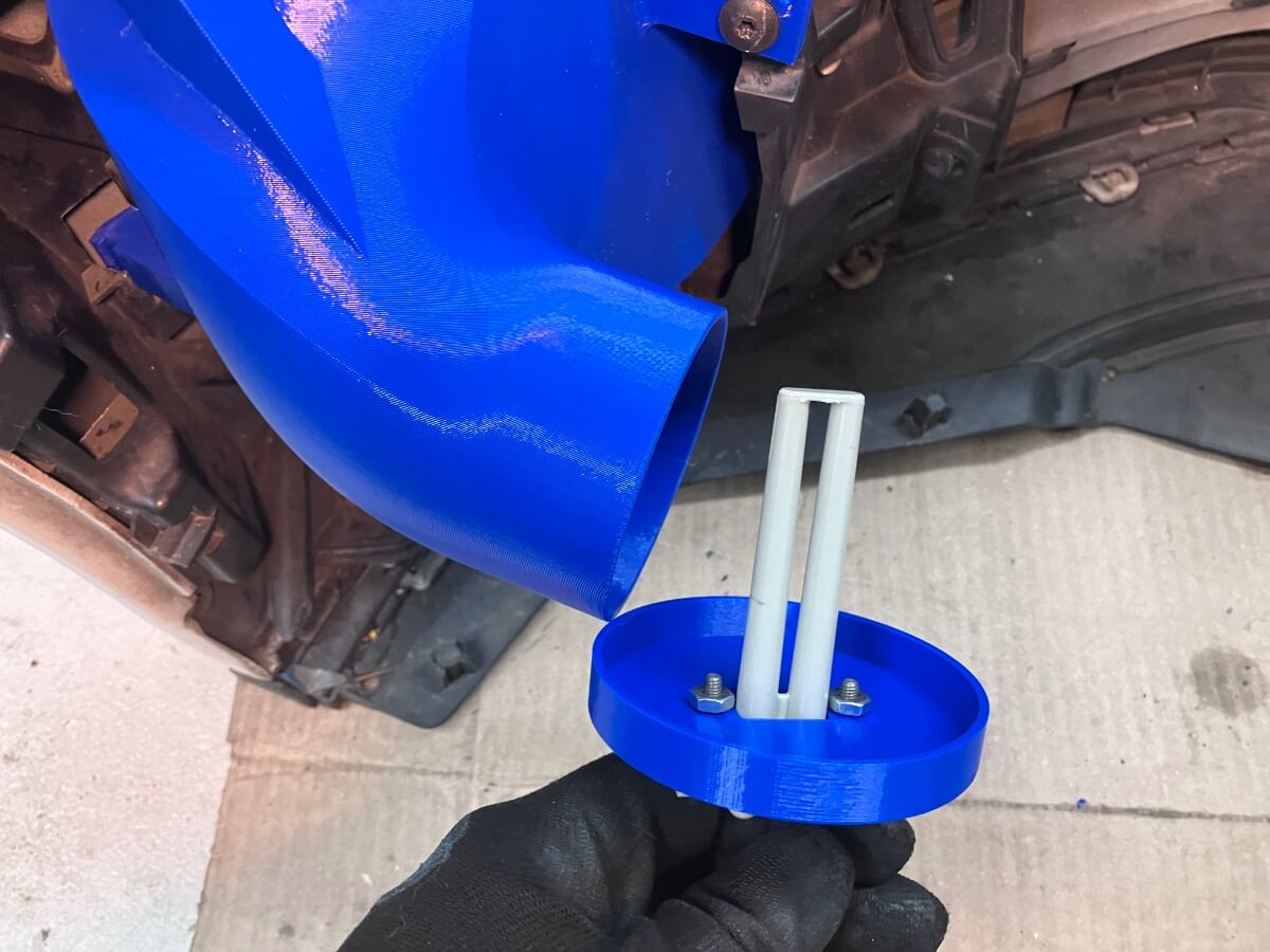
A pair of zip-ties worked well to hold the cap in place completing the duct installation to the bumper cover.
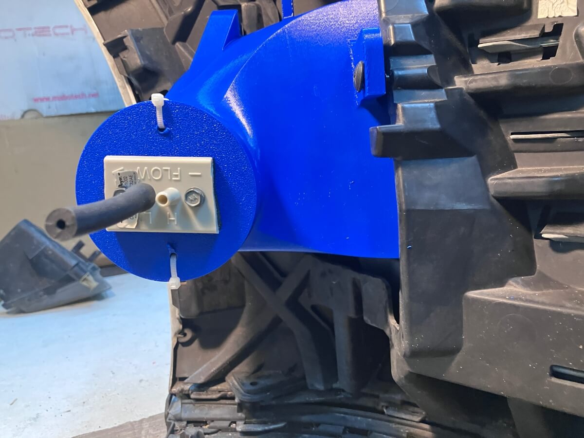
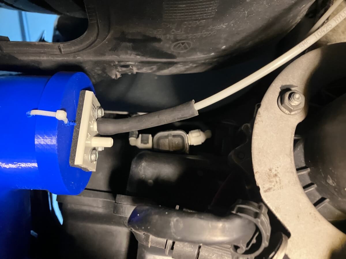
Once the bumper cover was reinstalled on the GTI a pressure line from a differential pressure sensor was attached to the AFS.
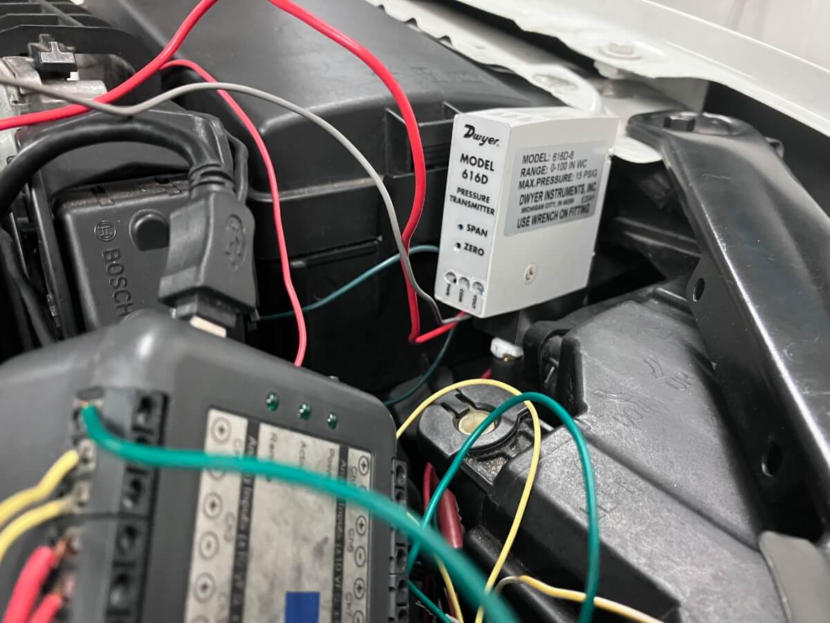
The pressure transmitter is wired into a DATAQ DI-149 data logger to measure the inches of water of static pressure inside the duct while driving the GTI.
Test:
With the bumper cover back in place the AFS installation is inspected.
The first test was made with a fan and a standalone differential pressure device.
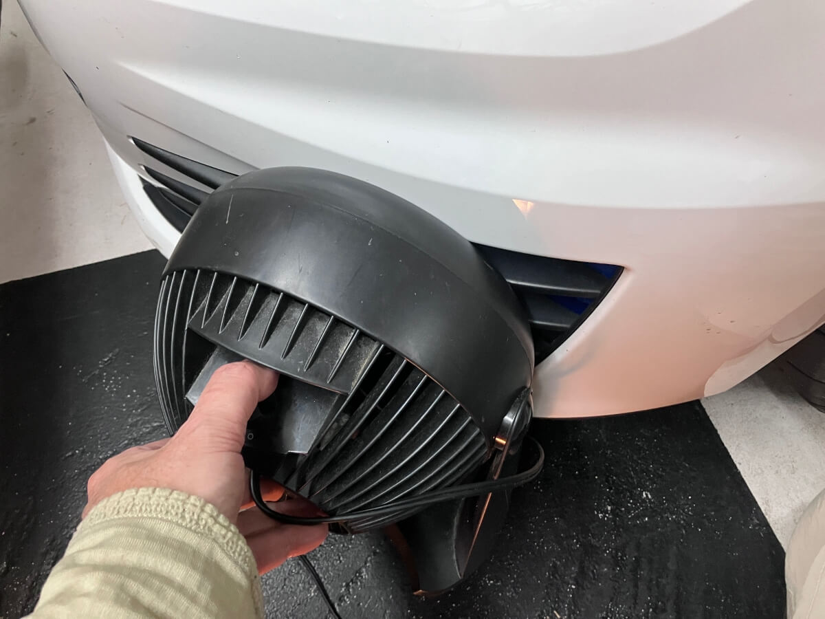
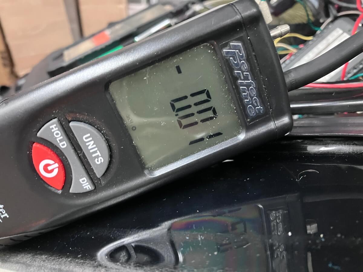
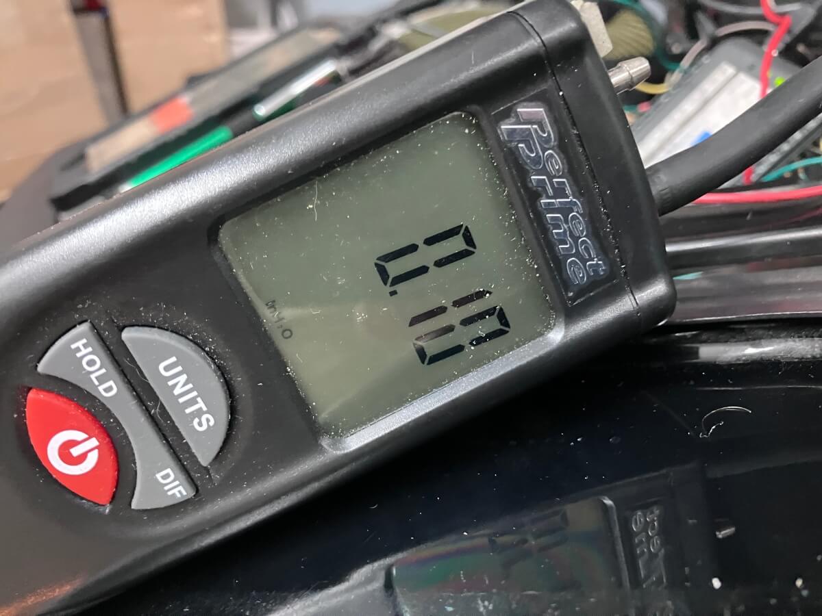
Without any airflow, the gauge shows right around zero (0). There’s a minor fluctuation of about +/- 0.01″ of H2O. With the fan on the highest speed and placed up against the bumper the static pressure increases to 0.1″ of H2O.
The amount of pressure increase was less than I was hoping for, but a drive on the street would provide more meaningful results.
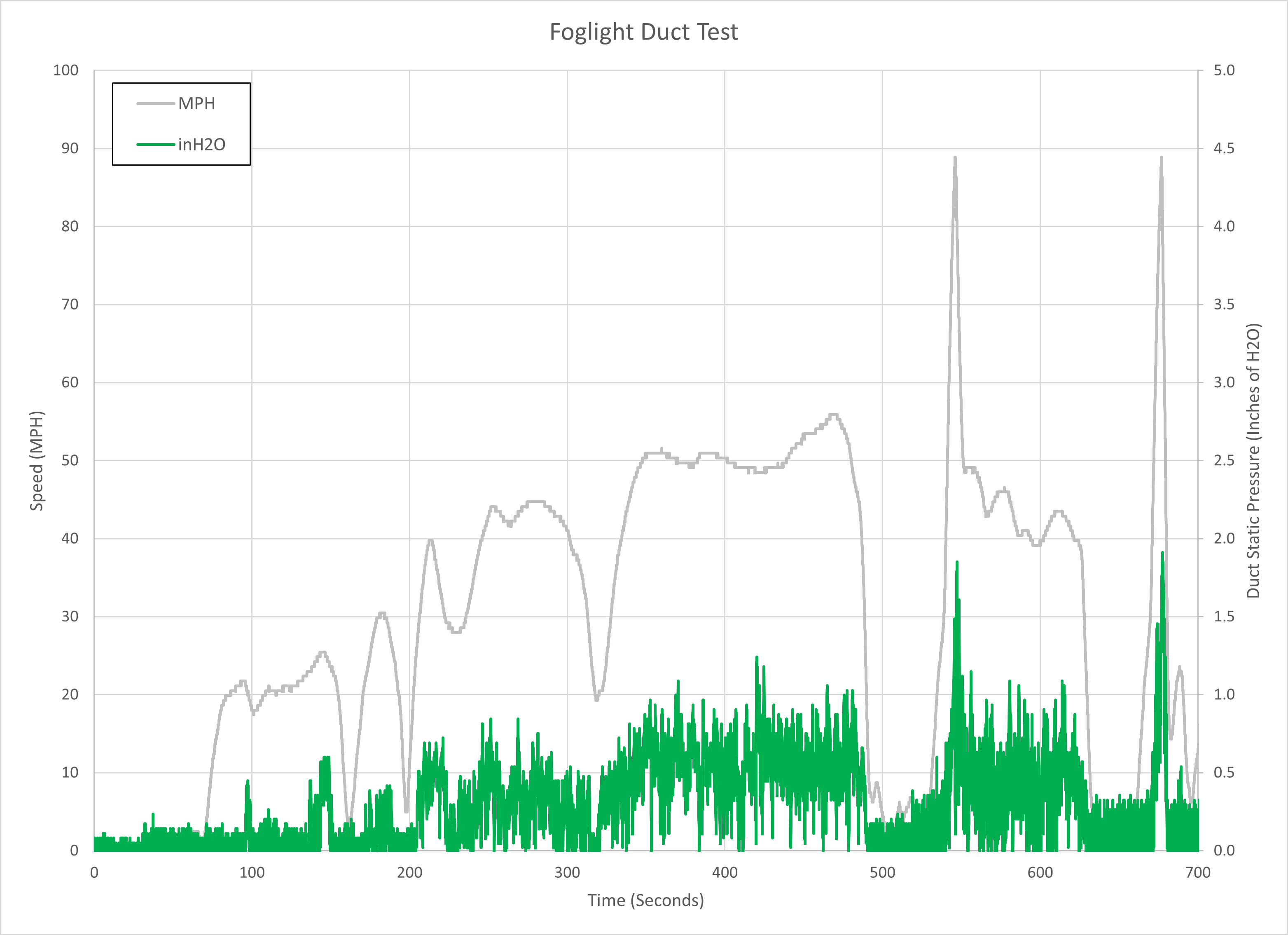
Pressure readings on the street were higher than with the fan.
Conclusions:
A foglight duct was made and then installed on my GTI along with a pressure sensor to determine the amount of static pressure inside the duct during street driving.
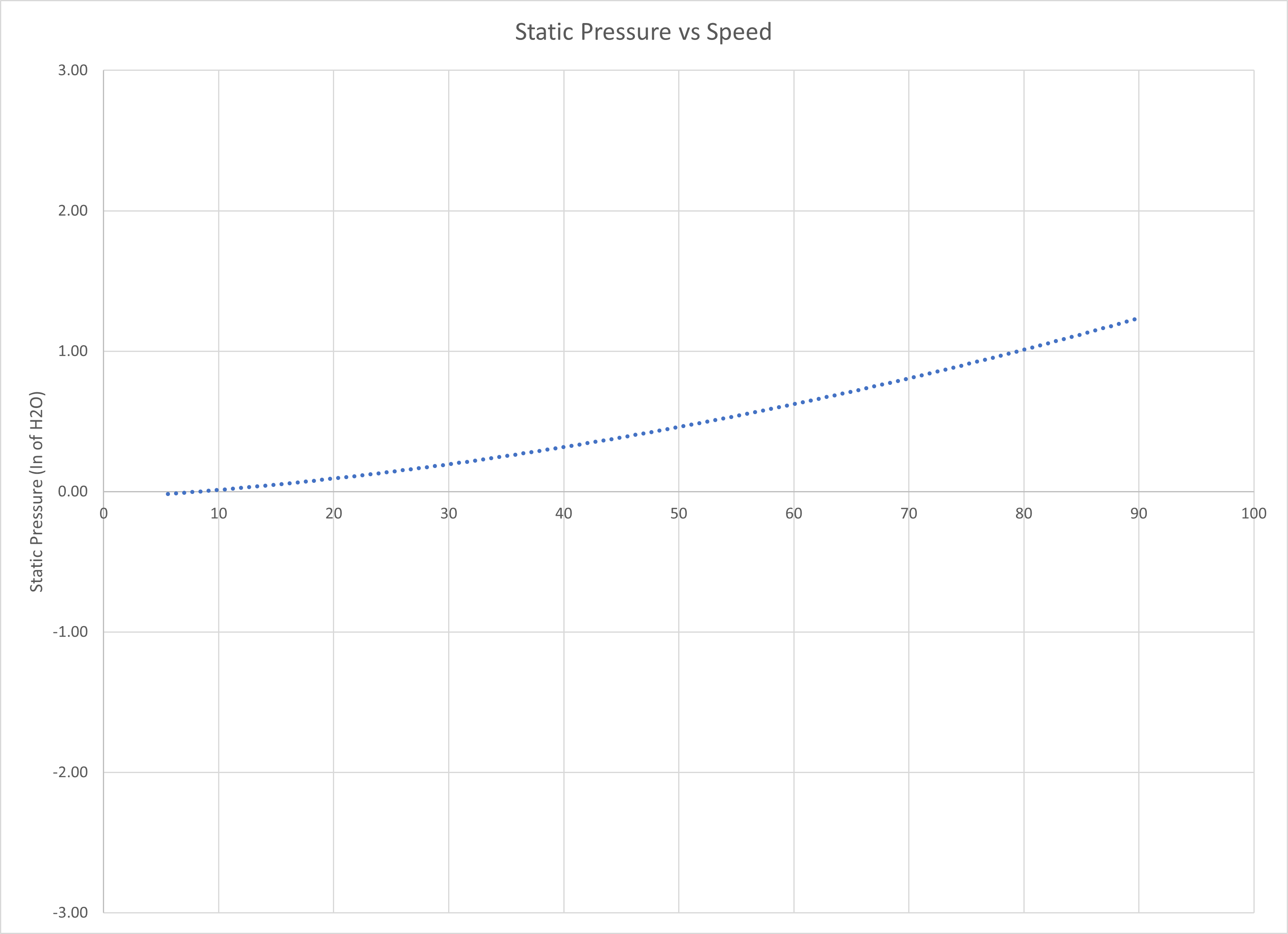
Measurements show a small increase in the static pressure inside the duct. This pressure increases with an increase in the vehicle speed.
Do you think there would be an appreciable delta if the engine would be ingesting air as opposed to your capped off testing?
The effect is already quite small which makes it difficult to measure accurately with the equipment I have. I’d expect the static pressure to decrease if the cap wasn’t in place and air could flow through. Using an open intake and measuring the air temperature, and possibly pressure drop, prior to entry into the turbocharger are what I think would be useful to measure to see if it has a meaningful affect.
Thanks for testing it out!
Was the differential pressure gauge measuring foglight vs engine bay? Because engine bay pressure is likely slightly positive compared to ambient anyway. Probably not a huge difference but maybe worth noting.
Lastly, on my car I eventually plan to seal between the duct and the bumper with foam. I suspect some air leaks into the bumper instead of the duct, probably a negligible amount though.
TBH my reasons for making this were not for pressure recovery or cold air, it was just to get rid of stock location intake parts so my radiator/IC air has a more direct path to my hood vents – so it’s cool to see any positive results with intake pressure.
The low pressure side of the differential gauge was plugged so it only read the pressure inside the duct.
I’m optimistic that there’s enough airflow to change the air temperature drawn in by an open intake. I agree that better sealing might help boost the airflow into the duct a little, but yes, it will probably be difficult to detect a small change.
I recently bought a 3D scanner (a proper one, not just photogrammetry using my phone) so expect I will be refining this design to fit better.