Background:
Questions about the vacuum level inside the PCV port of the Mk7 turbo inlet elbow led to some testing of this property.
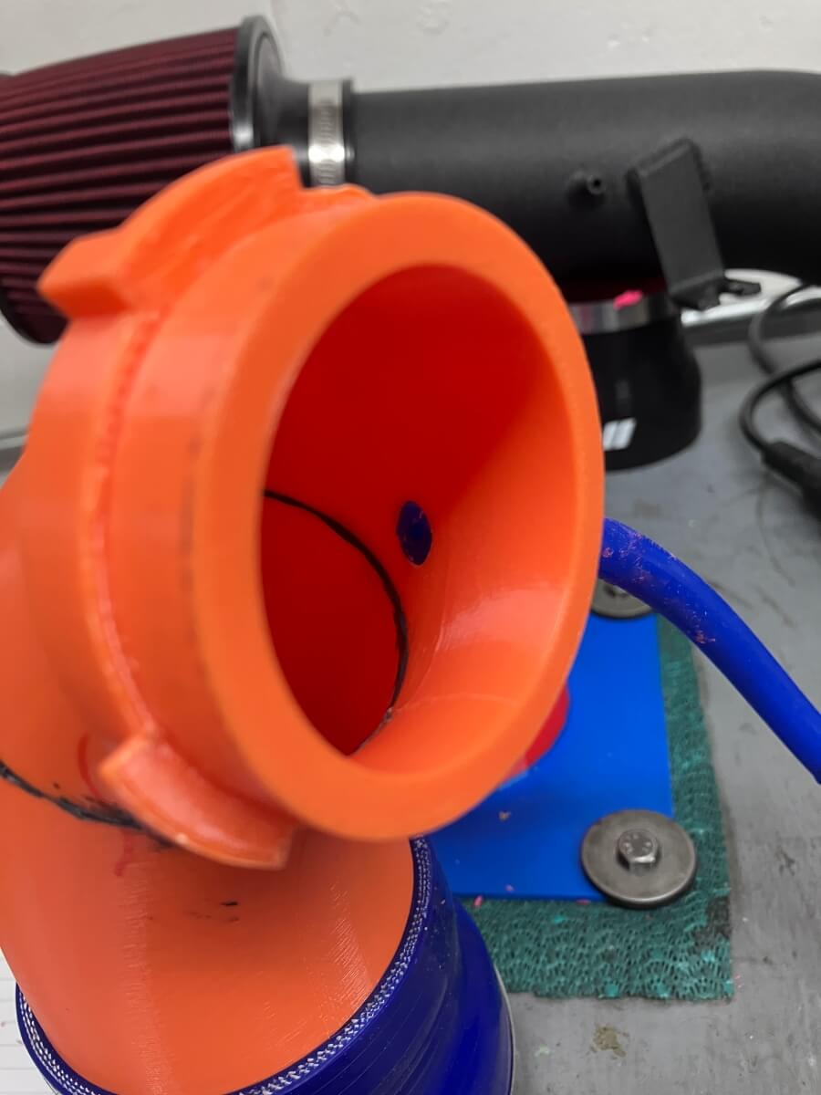
Aftermarket elbow:
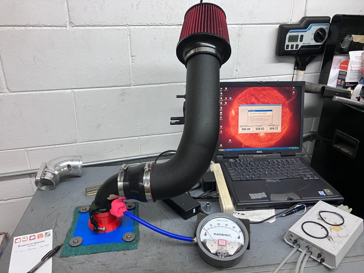
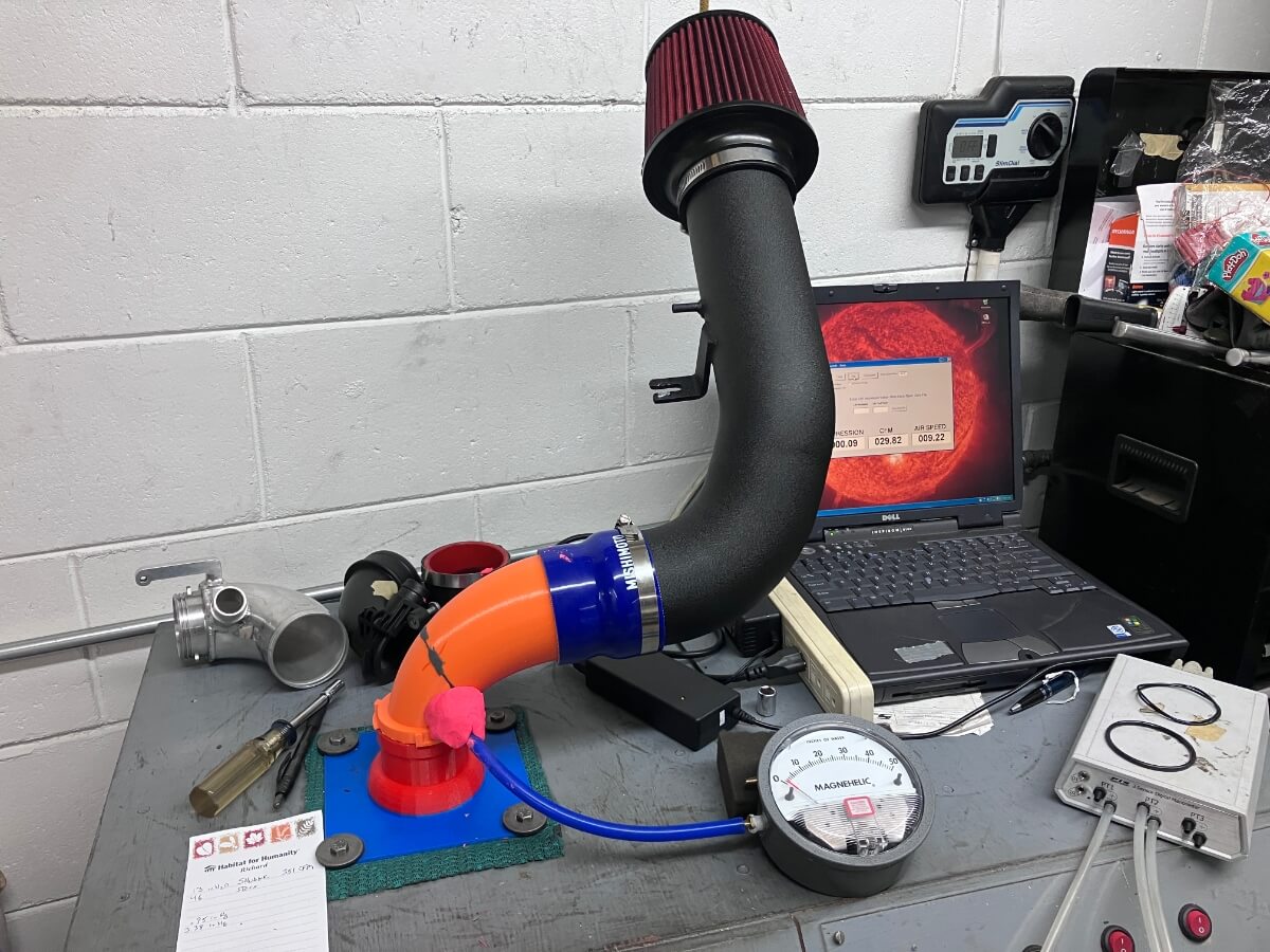
Here an aftermarket elbow is connected with a CTS Turbo intake and a differential pressure gauge is used to read the vacuum at the PCV port.
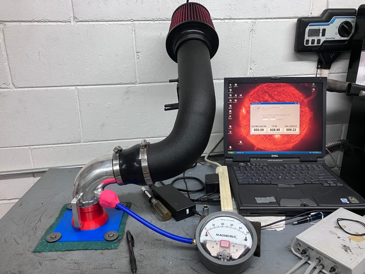
To gauge the relative amount of vacuum between components the flow bench is operated at a steady 350 CFM and the Vacuum measurement is then recorded.

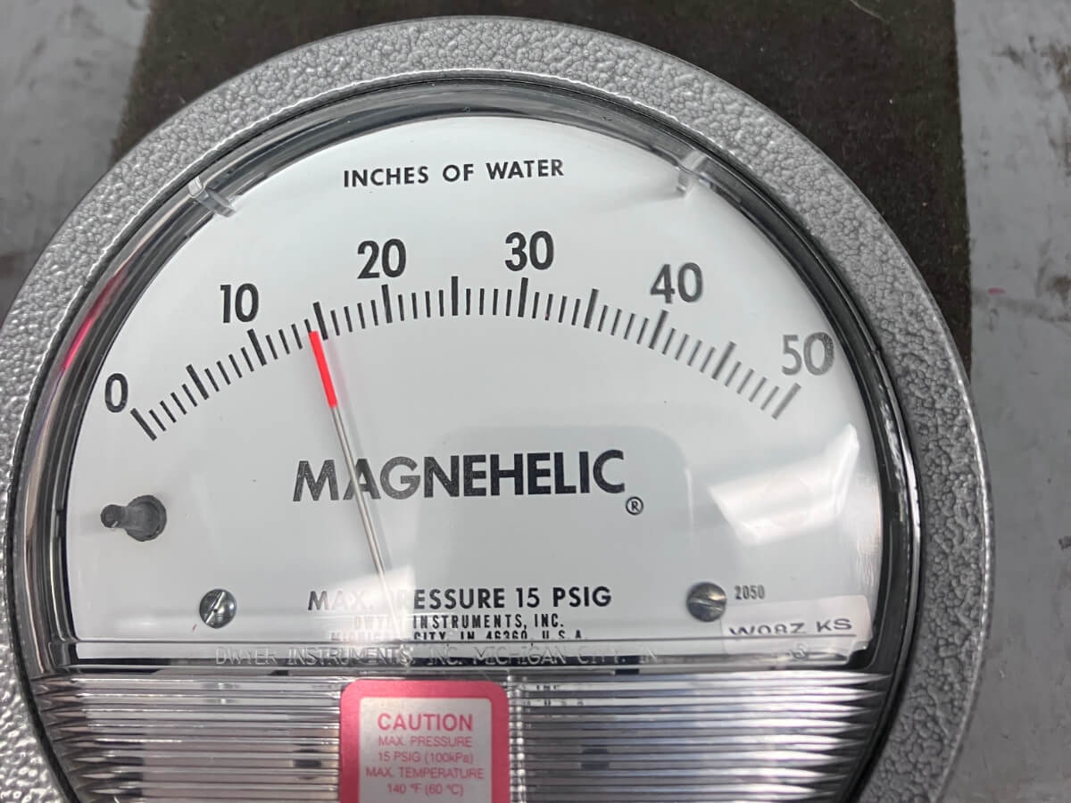
The vacuum created by the aftermarket elbow is 13″ of H2O at 350 CFM.
Stock elbow:
Next the GTI stock inlet elbow is swapped in for the aftermarket elbow and the procedure is repeated.
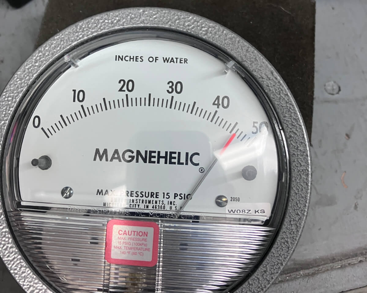
The stock TIP generates a vacuum of 46″ of H2O at 350 CFM.
Prototype elbow:
Next, a prototype elbow that gradually tapers from a 3″ opening to a 49 mm outlet is tested.
This elbow does not have a PCV port, so the vacuum is measured where the port would be.
The goal of this experiment is to find out if the taper of the pipe is a strong contributor to the vacuum generated near the PCV port location. The taper of the pipe will increase the airflow velocity, which will correspond with a decrease in the static pressure.
The vacuum created in the prototype elbow is 14″ of H2O at 350 CFM.
This is barely higher than the aftermarket elbow and suggests that the pressure reduction resulting from the velocity increase is small.
Modified aftermarket:
A modification is made to the aftermarket elbow by pressing a small amount of Play-Doh to the side of the pipe just upstream from the PCV port.

The Play-Doh is covered with a piece of tape to keep it from being pulled down through the inlet by the airflow.
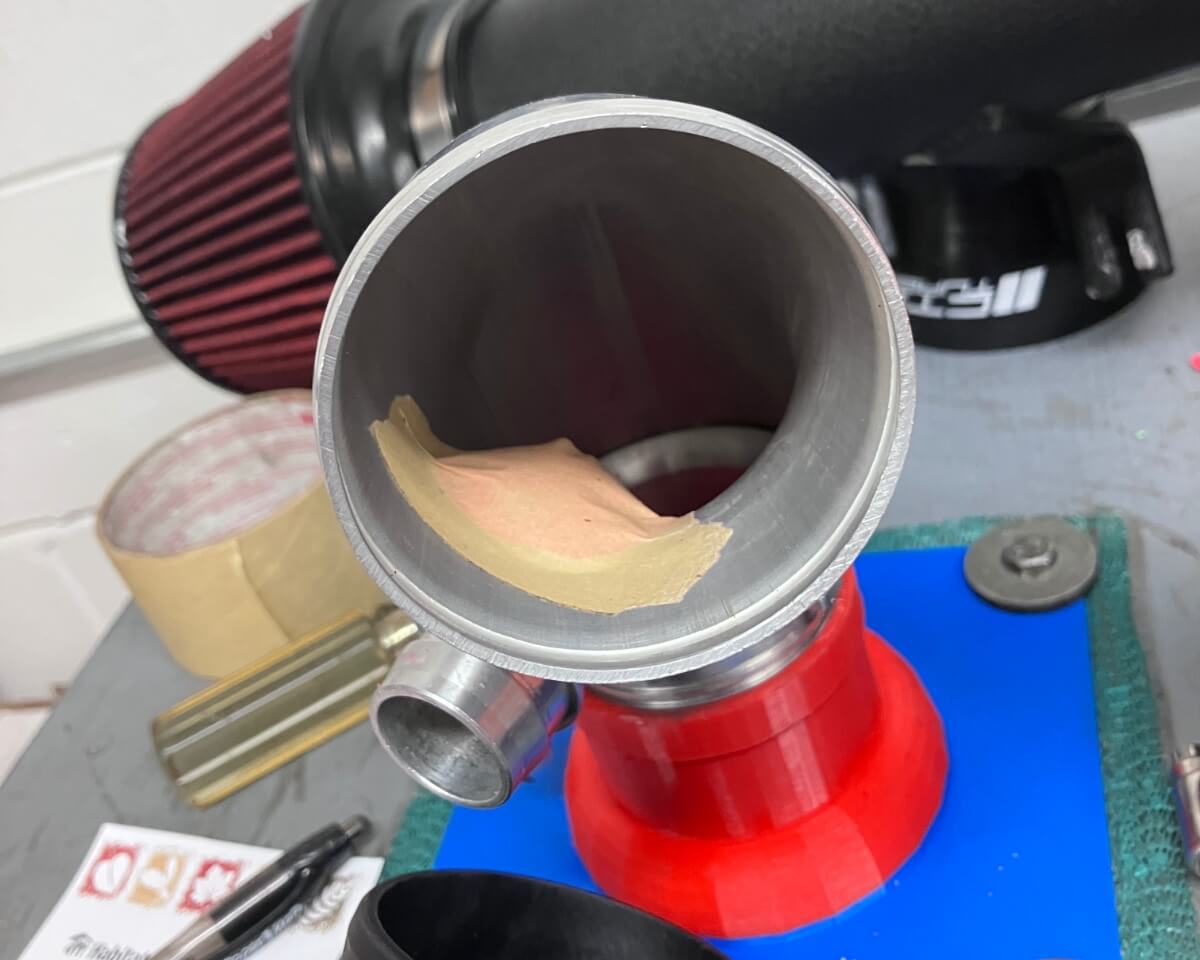
The vacuum increases slightly to 21″ of H2O @ 350 CFM with the addition of the bump before the PCV port.

Thanks for helping with this research!
You’re welcome! I’m glad I was able to help out in a small way.
Excuse my ignorance but what are the benefits/downsides of the different vacuum levels?
As I understand, it plays a part in how efficiently the PCV system functions. Tony who authors Data Driven MQB has been doing research into this and has much better information than what I can provide.