Background:
About two months ago results were posted from flow tests using a second prototype TIP. In this post, a third design is flow tested, and results are compared with previous tests.
System under test:
The latest prototype was made with the intent to try and maximize the airflow through the inlet elbow while also increasing the vacuum at the PCV port.
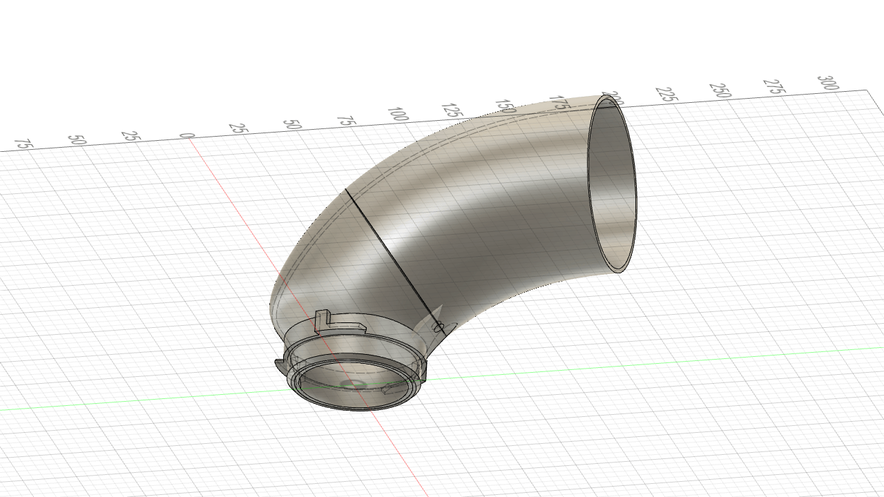
To accomplish this the taper to a 49 mm outlet diameter is delayed until just before the adapter ring that holds the elbow in the turbocharger compressor cover.
Along the inside edge of the elbow leading into the adapter ring is a bump that is based upon an airfoil upper surface which has a function of increasing airflow velocity to increase the vacuum at a hole made in the elbow which would lead to the PCV system.
Test Procedure:
Two measures are made with the elbow. One is the maximum flow rate through a CTS Turbo intake when using the TIP, and the second is the vacuum at the PCV port hole when the airflow rate through the intake is held at 350 CFM.
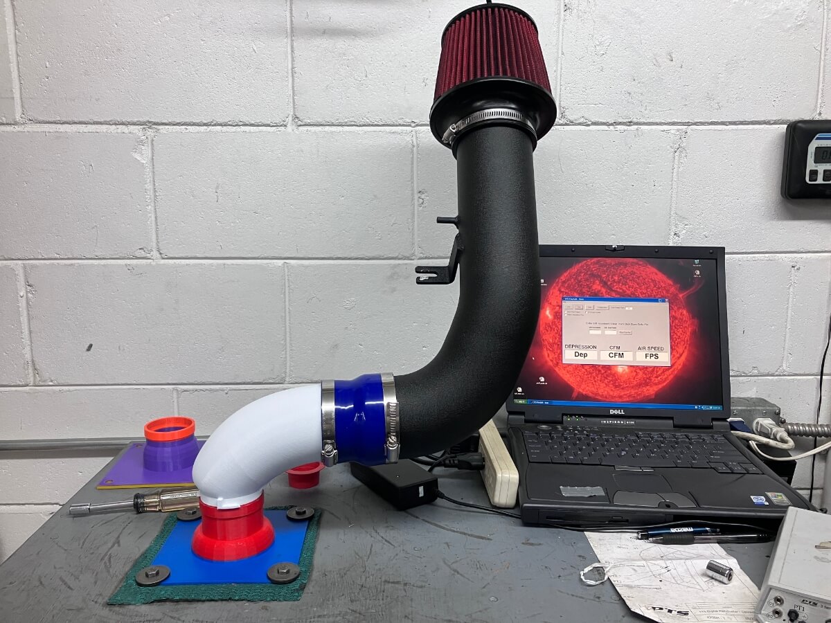
The TIP is attached to the CTS intake on one end and the other is attached to the flow bench using an adapter that simulates the inlet of the IS20 and IS38 compressor cover just before the compressor wheel.
The flow rate through the intake is measured at a test pressure of 28″ of H2O.
The second test is configured the same except a manometer is attached to a length of small plastic tubing which is placed in the PCV port hole, and the area around the tube is sealed using Play-Doh.
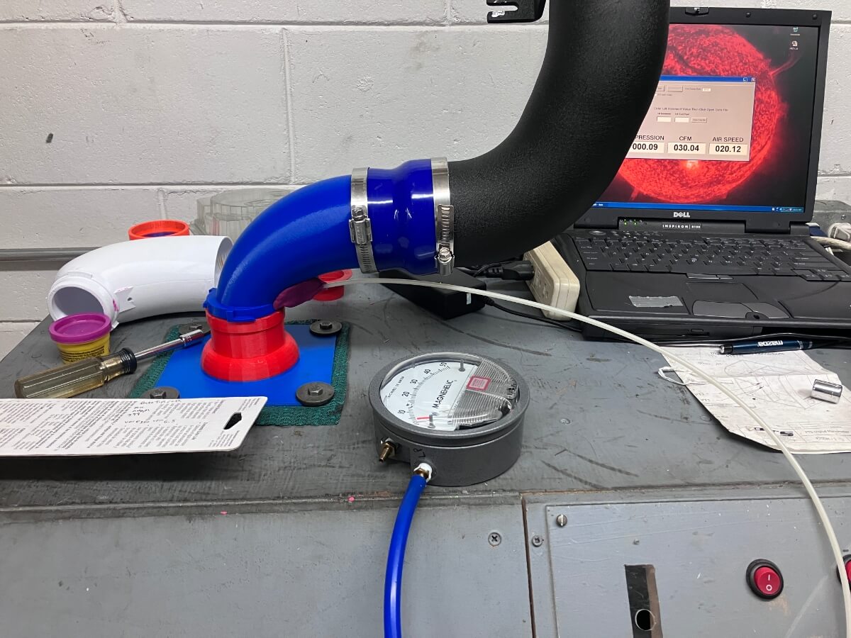
The airflow rate through the intake is increased to 350 CFM and at that flow rate the vacuum at the PCV port hole is recorded.
Test Results:
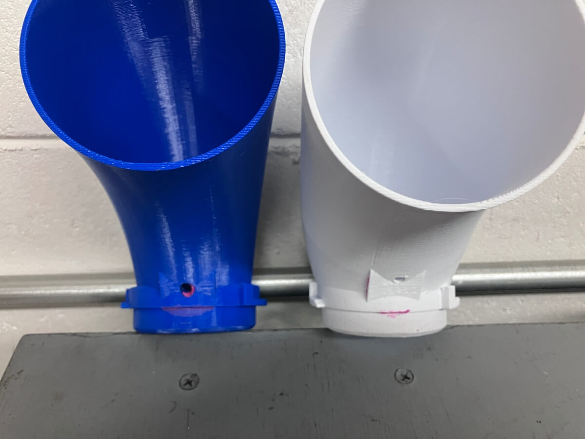
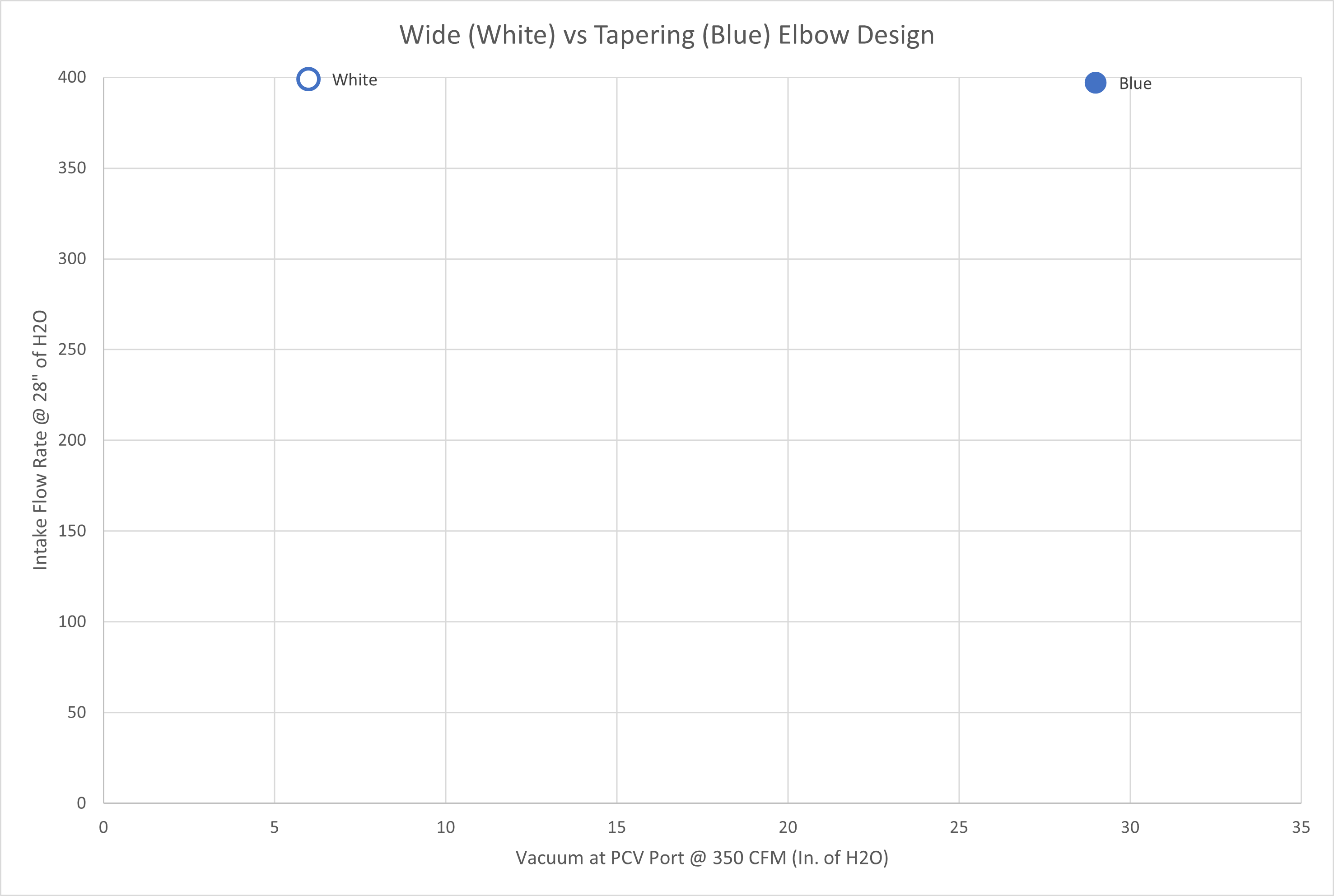
The intake using the white TIP flows 399 CFM @ 28″ of H2O.

Using the blue TIP the intake flows 397 CFM @ 28″ of H2O.
Measurement of the vacuum produced readings of 6″ of H2O from the White TIP and 29″ of H2O from the Blue TIP.
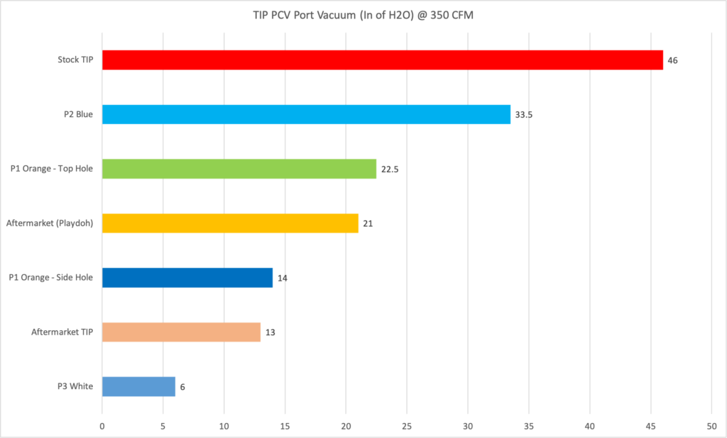
The chart below shows how there is a small difference in the flow rates using the stock turbo adapter, but a large difference in the vacuum at the PCV port hole.
Comparing all of the results thus far, the latest prototype does not perform well in generating a vacuum.
Conclusions:
A third protype turbo inlet elbow was designed and tested to see if increased airflow and increased vacuum could be realized.
The new design does yield a slightly higher airflow compared with the previous design, but the vacuum generated has decreased substantially.
One potential variation to investigate is the relocation of the hole where the pressure measurement is being made. This hole is slightly further upstream when compared to the location on the Blue TIP (see second picture in post). By moving the pressure pickup point to a location further downstream the inlet pipe diameter will be smaller, resulting in a higher airflow velocity. This increased velocity may correlate with an increase in vacuum.