Background:
A few weeks ago I made some initial measurements of the vacuum generated at the inlet elbow PCV port with the stock turbo inlet elbow, an aftermarket elbow, and a prototype I was working on.
I had an idea to try and increase the vacuum inside the prototype elbow by building a raised area on the inside of the elbow.
Elbow Modification:
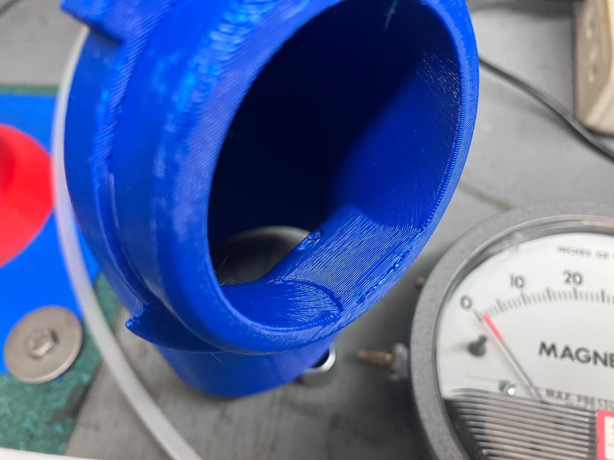
I stayed with the existing prototype elbow design and leveraged a high-lift airfoil shape to create the raised area.
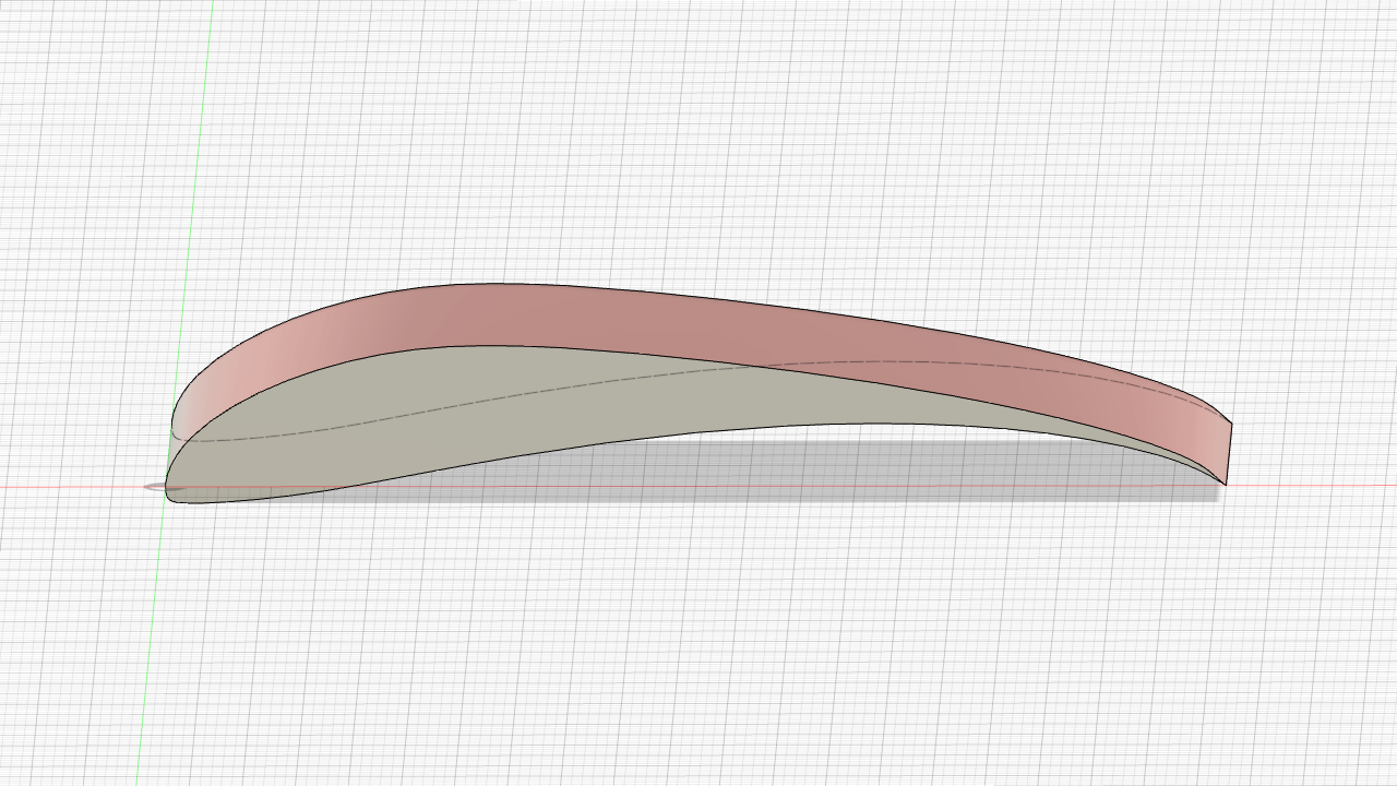
The upper half of the airfoil was added to the elbow:
The update printed well which setup conducting a second flow test.
Flow Test:
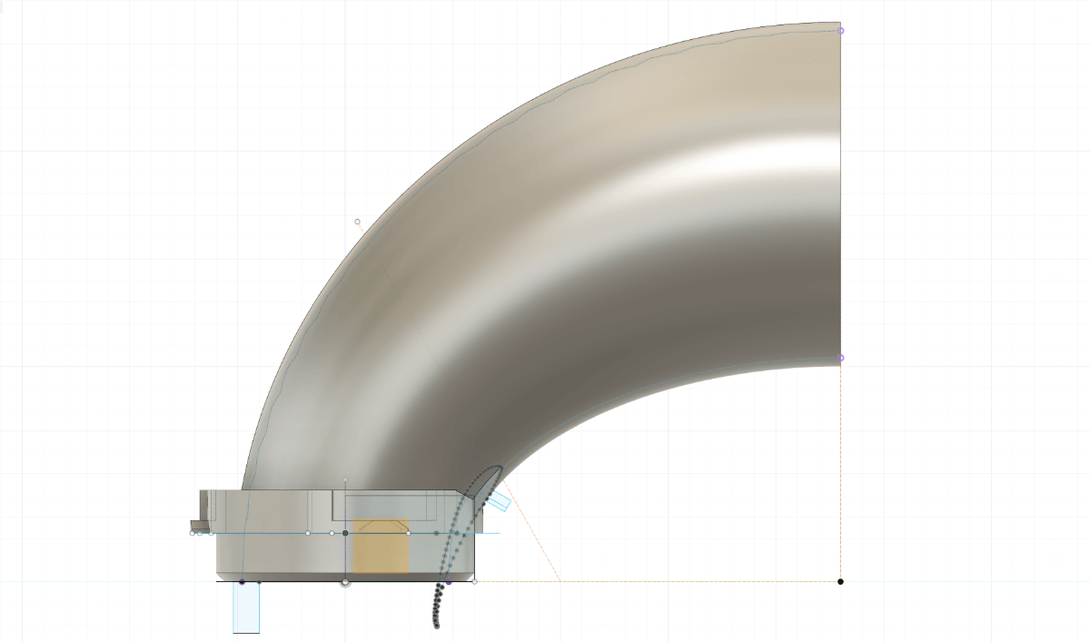
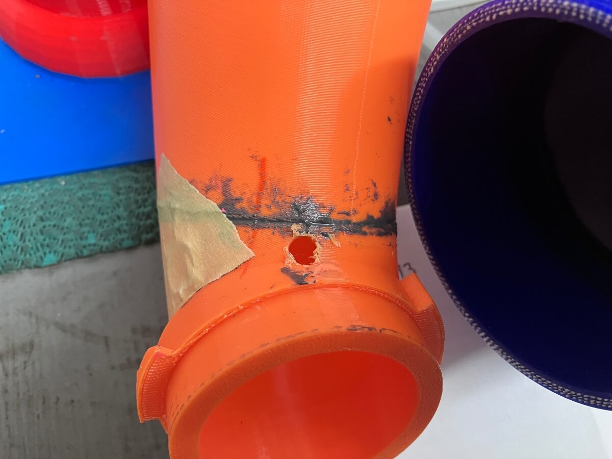
This second prototype included a change that moved the measurement port to the center of the elbow. The goal of this change was to try and take advantage of what should be a local high-velocity area.

Since this meant two changes were being made a second hole was made in prototype one (1) to measure the vacuum at the center of the elbow, shown below:
Prototype 1 was then retested:

The new location showed a slightly greater vacuum at 22.5 inches of water at an airflow rate of 350 CFM.
The other port location measured 14″ of H2O @ 350 CFM.
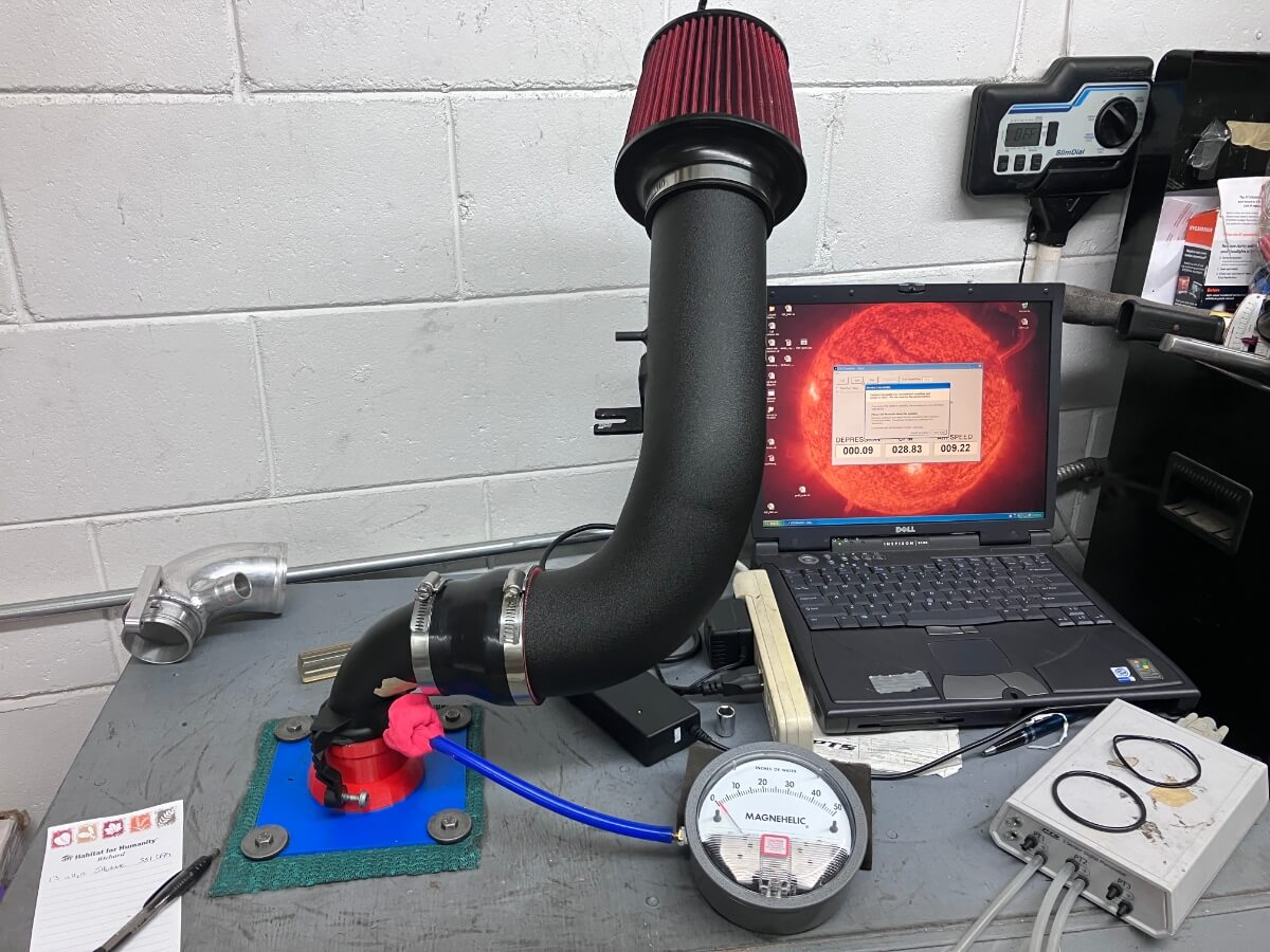
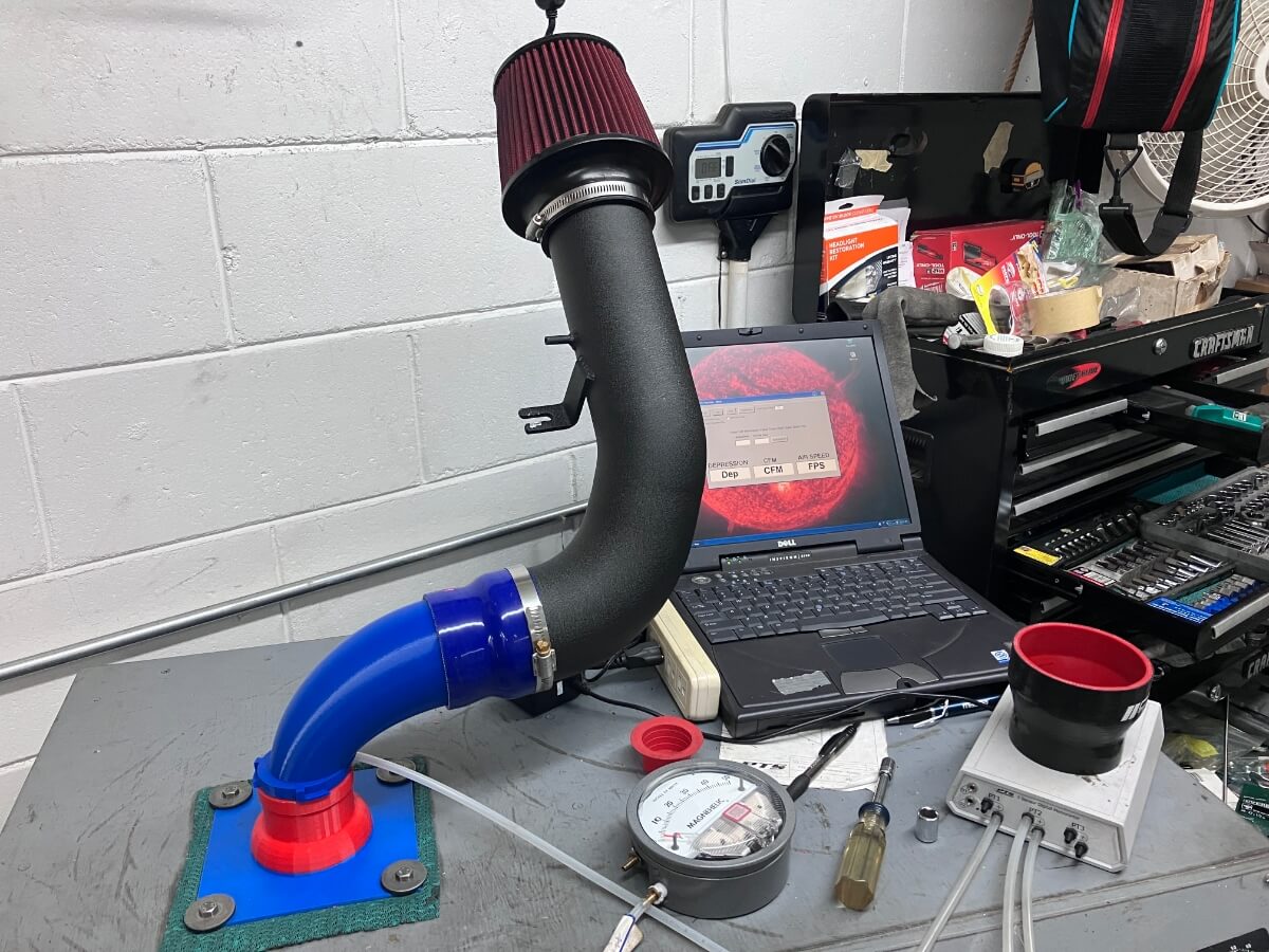
Next, the second prototype was configured for the flow test:
An improvement was recorded with the vacuum increasing to an average of 33.5 in of H2O @ 350 CFM:
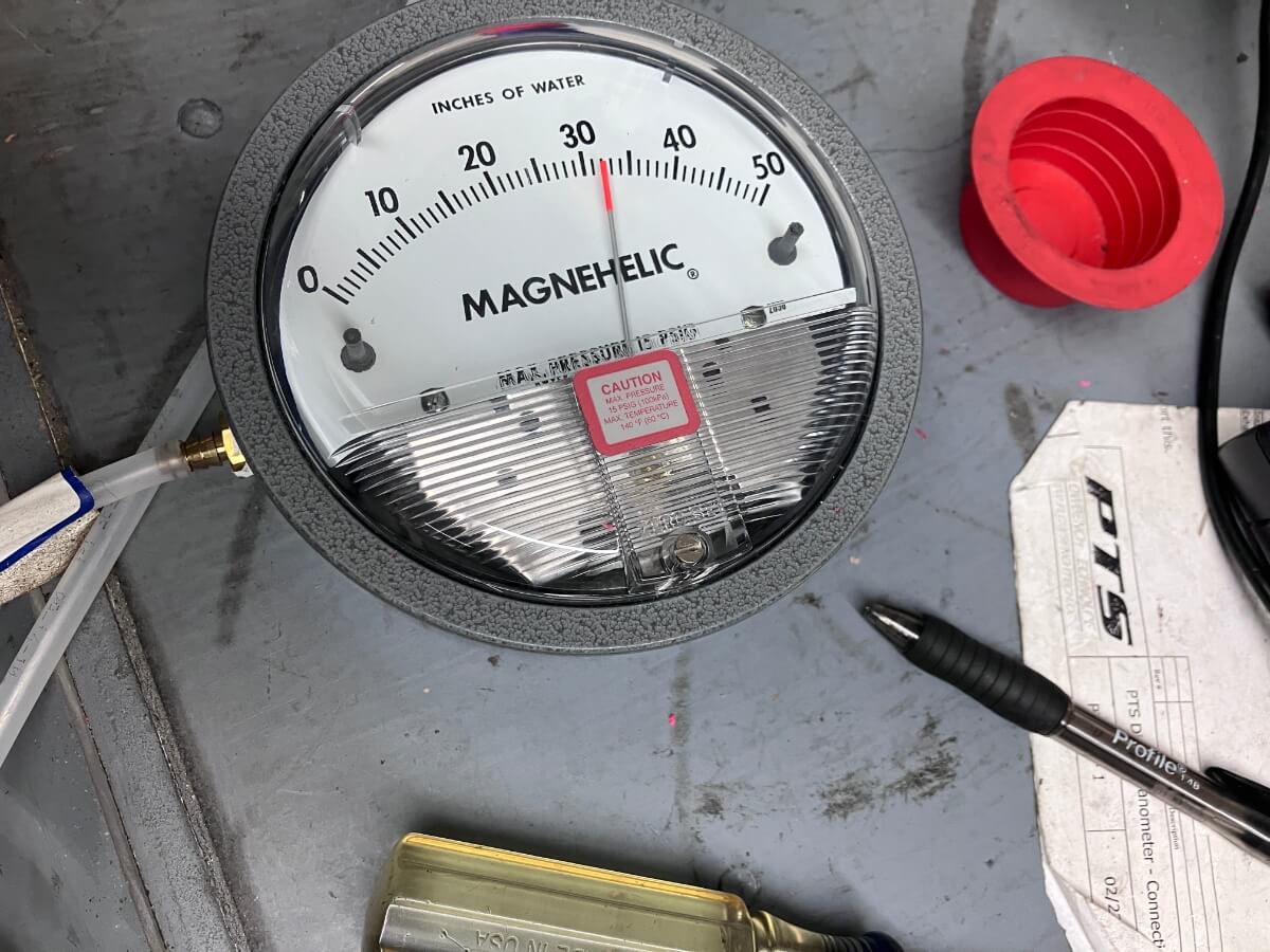
Note: The picture shows a reading of 32″ of H2O because turbulence causes pressure fluctuations and the moment the picture was captured the reading was down from the average.
Results Comparison:
A summary of all test results to date is shown on the chart below:

Conclusion:
A prototype turbo inlet elbow was made with an internal raised area to determine the effect on the vacuum at the raised area.
A flow test showed an increase in the vacuum level from 14″ of H2O @ 350 CFM at the OEM port location with a prototype elbow up to 33.5″ of H2O @ 350 CFM at a center location with a raised area inside the inlet elbow.
Might be worth revisiting the Inlet tests you performed earlier with this new perspective.
I’ve measured two aftermarket TIPs and have two others I could measure in the future. The two I measured created a similar amount of vacuum. I don’t recall any that I tested in the past having a design feature that would promote high vacuum at the PCV port.
Could this actually add a strain on the pcv? Been thinking about deleting the whole thing using the racing line plate or the 034.
I think the research Tony has posted at Data Driven MQB is better for addressing that question.
Good advice. Thanks!