In a previous post the setup for ram air testing was described.

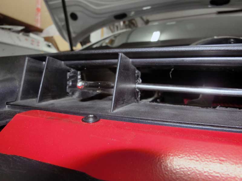
Before collecting data the addition of a piece of foam to the intake was made to ensure that ram air at the inlet to the intake would be maximized for each operating condition.

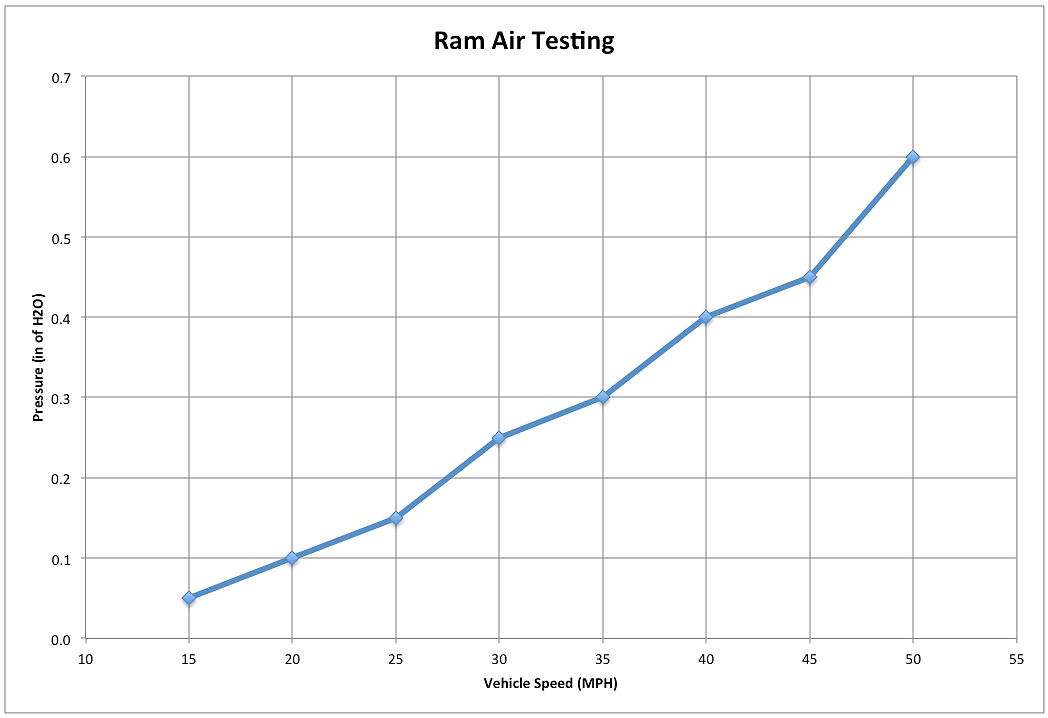
Pressure readings at the intake were made at the following speeds: 15, 20, 25, 30, 35, 40, 45, 50 mph.
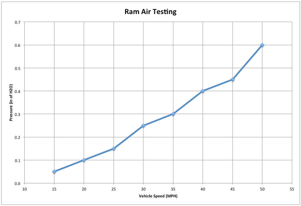
The measurement taken at each speed is shown on the chart below:

With increasing vehicle speed the static pressure at the intake inlet area is increasing.
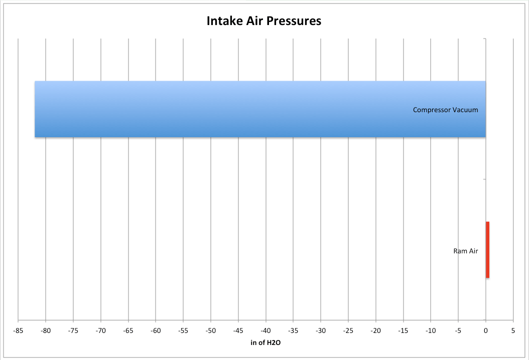
Although there is a ram air effect taking place at the inlet opening, when this positive pressure is plotted versus the vacuum being generated at the turbocharger compressor inlet the magnitude of the ram air effect is put into perspective.

The chart above shows the compressor inlet vacuum at full boost on my IS38 turbo and the ram air positive pressure at 50 mph. As the chart makes clear, the ram air effect is negligible in comparison to the vacuum generated by the turbocharger.
Next will be a look at closing the intake air scoop to see what affect, if any, there is on the ram air pressure.


https://www.getunitronic.com/news/unitronic-tech-article-turbocharger-air-duct
A common modification on the GTI is to cut holes into the front intake part on the driver side. This accomplishes opening an additional path for air to enter the duct. This is an alternate method to the product Unitronic offers, and what I’ve done on my GTI.
Did you note this disclaimer: “*Trendlines used to exemplify wastegate actuator position to aid in cognizance.” It does not seem that the chart is actual data.