
Design changes:
For the next change to the MGM7 intake design, I’ve swapped air filters to a Vibrant filter with a 7″ inlet.
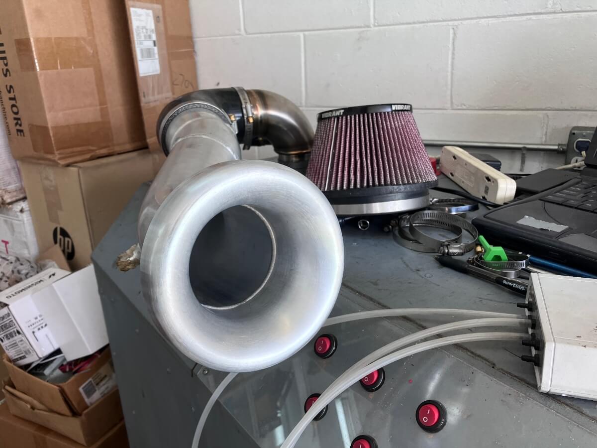
The Vibrant air filter I have been using has worked very well and has a 6″ inlet. Entertaining the idea that bigger might be better I ordered the 7″ inlet filter which is getting close to as big a filter that I can probably fit into the engine compartment.
The picture below shows a mockup I made of the filter to see if it would fit.
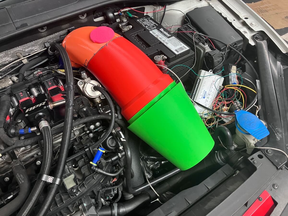
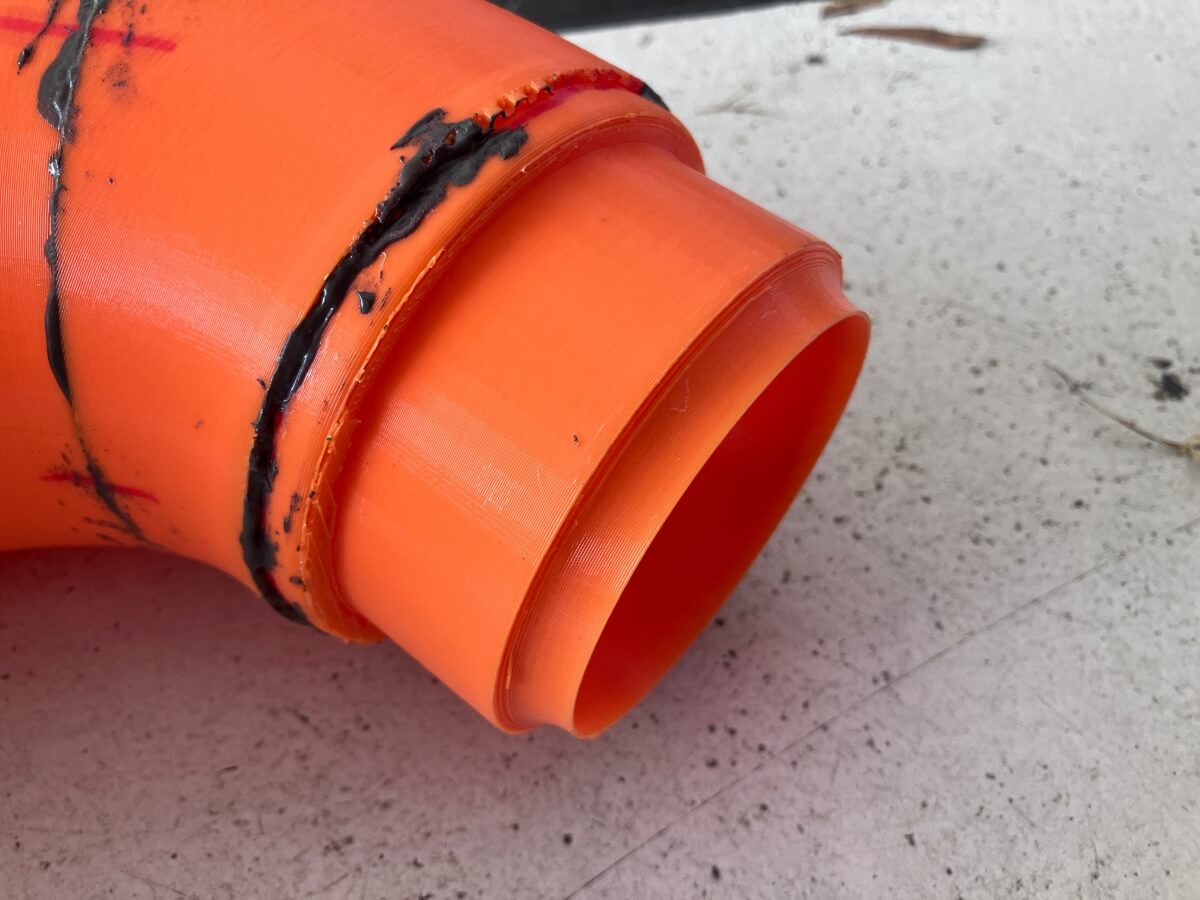
As I mentioned in the previous post, this iteration of the design has focused on changes to the inlet end and the outlet end.
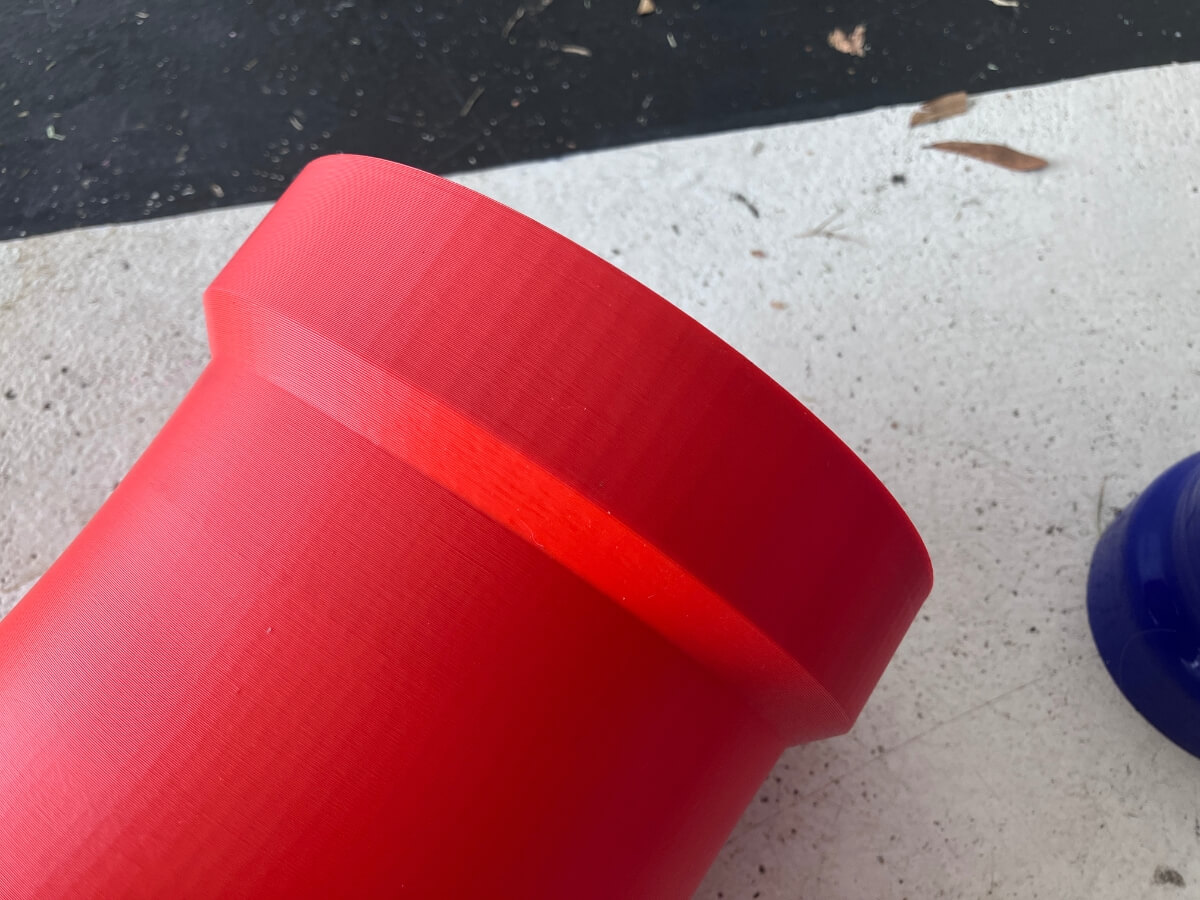
The change of the air filter to a 7″ inlet forced part of the modification, but another was the addition of a lip that would give me an idea of how far to insert the filter flange on the inlet tube.
The Vibrant filters are advertised as being made for use with a velocity stack, such as how the DBV2 intake is designed,
but in the case of the MGM7 I’ve forgone the use of a velocity stack in favor of maintaining a larger diameter pipe for as long as the space in the engine compartment allows to keep air flow velocity down.
The addition of the lip should help to ensure that a smooth transition takes place from the filter to the inlet tube by keeping the placement of the air filter consistent.
The more significant change to the intake is on the outlet end. Because at some point the intake must narrow to join with an inlet elbow, and then connect to the even smaller turbocharger inlet, this is the part of the intake where air velocity starts rising, and pressure losses start increasing with the square of the velocity. Screwing up at this end will negate all of the positive effects that the other portions of the intake produce.
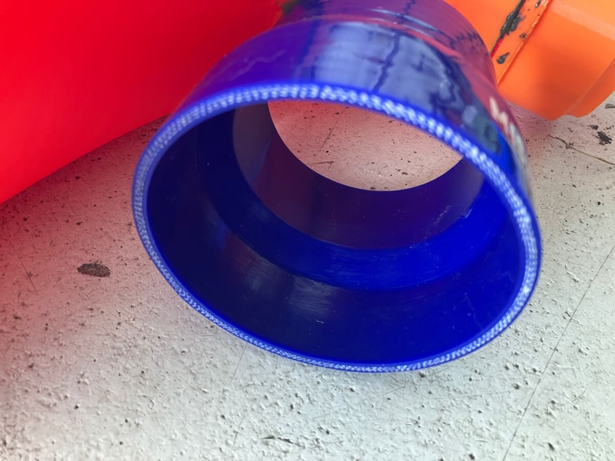
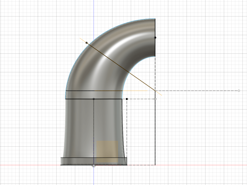
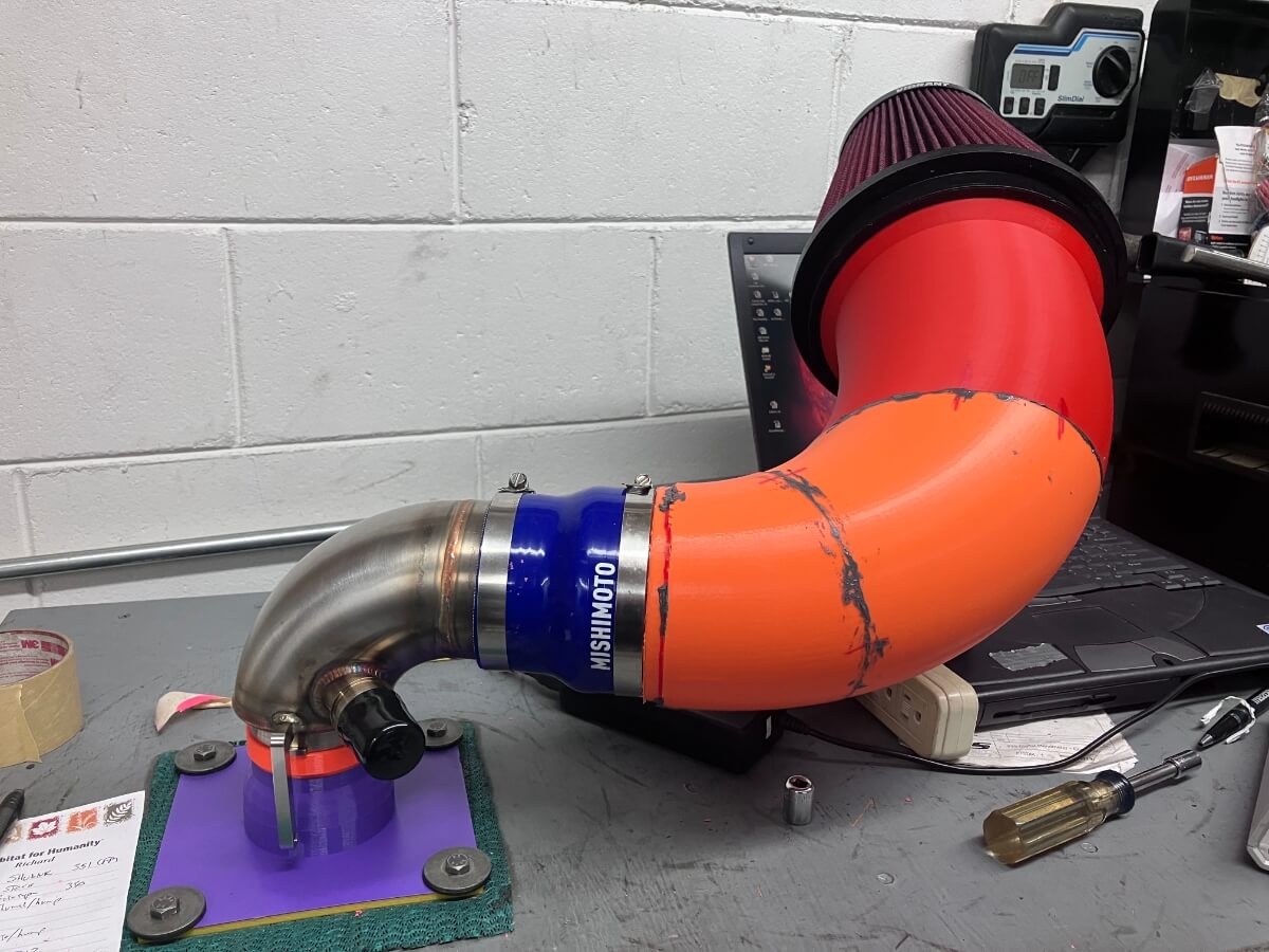
One part that looked like there was an opportunity to improve was the silicone reducer that transitions the Beta-5 intake outlet from 3.5″ to the elbow inlet of 3″.
Note: In the Beta-4 design the intake outlet was 4″ in diameter and it used a silicone reducer to transition to 3″ for entry into the elbow. With Beta-5 I’ve used the back portion of the intake to begin to neck down to 3.5″ so that the transition is over a greater distance and more gradual. Again to reduce pressure losses.
As the image above shows, this transition of diameter using the reducer is over a relatively short distance, and redirecting high-speed airflow over a short distance is a recipe for pressure loss.
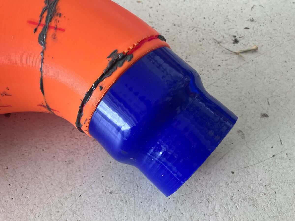
To address this concern I designed the end of the intake to fit into the reducer far enough to replace the reducer’s transition region with a shape of my choosing.
Once joined with the reducer the inlet fits snugly and provides a more gradual transition.
With these changes made the new design was printed and assembled on the flow bench for testing:
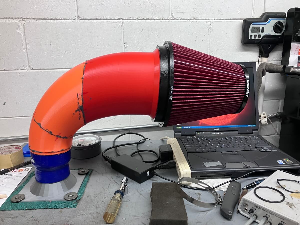
The standard for testing the intakes in this development effort is direct to the flow bench, shown above, at a depression of 13″ of H2O.
I also ran a test using a DBV2 inlet elbow, shown below.
Another variation was the Beta-5 intake joined with a stock turbo inlet elbow and an adapter that simulates the stock IHI turbocharger.
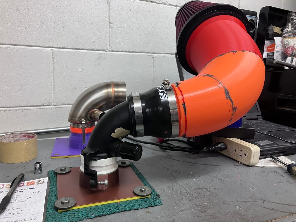
In the case of the stock TIP, this setup represents a decrease in diameter from 7″ at the opening to 1.9″ at the outlet. With such a small outlet I don’t have any delusions that the airflow rate is going to be any higher than a run-of-the-mill commercial intake into a stock turbo.
MGM7 Beta-5 Test Results:
The Beta-5 intake showed a good increase in airflow rate versus the Beta-4 design, setting a new record of 621 CFM @ 13″ of H2O. This represents a 4% improvement.
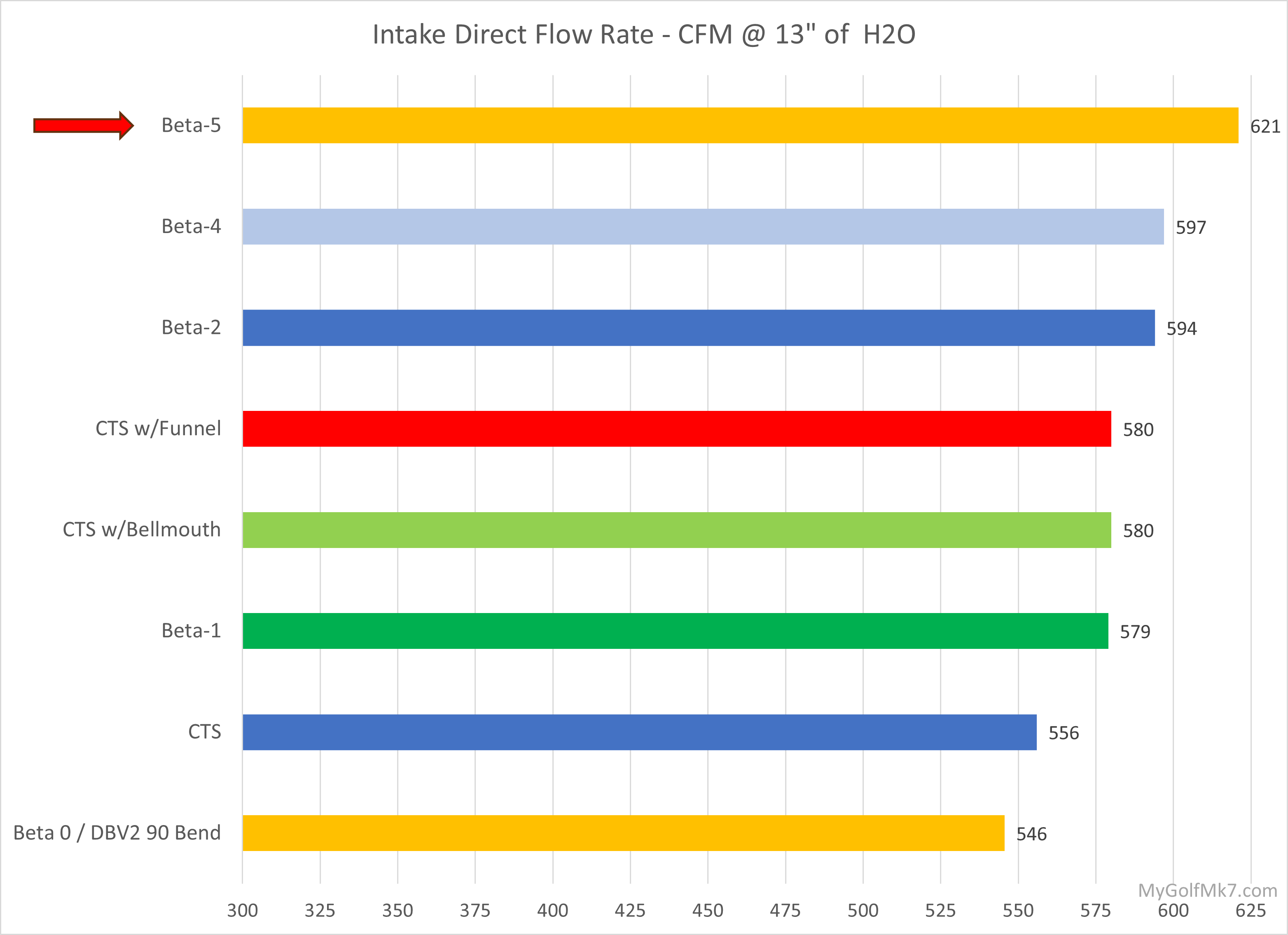
Compared to the highest flowing commercial intake that I have tested, the 3.5″ CTS intake, the Beta-5 achieved 11.7% more airflow.
Next steps:
More work is needed to understand the constraints imposed by the engine compartment. The filter fits, and the transition to the reducer is working well, the middle section of the intake remains a question mark.
Im making something similar for SN95 Mustang, with a custom headlight intake I designed and 3D printed, and I have seen a direct correlation between flow and total filter area, the new 7″ ID filter seems to also be longer, I’d be awesome to test a 6″ ID filter that is longer and has the same aprox outer filter area as the 7″ ID, to see what of the gains are from the bigger filter area vs the 7″ pipe! being a more compact, easy to package combo if the 6″ with the same filter area works as good
I decided to go with the 7″ inlet diameter to slow the air speed compared with the 6″ inlet. Probably very minimal, but since the filter fits in the available space, and the smaller Vibrant air filter flows well, I decided to move ahead with this filter. In addition to the filters I discussed in the filter test post I also acquired an AEM filter that’s a similar height with a 6″ inlet and ran a test with it. It was no better than the other filters I tried.
How do I go about getting one of these made. Would you sell?
This version needs some work to fit well in the engine compartment. When I finally finish development, I’ll look into options for making it available for others.
No worries a good 70CFM gain over the traditional CTS intake is amazing. What kind of gains roughly would 70CFM look like on your setup? I’m currently running a stage 1 powermax turbo and was gonna flex tune the car. But I think I might wait for this intake before I get the tune.. Do you no roughly how long development will go on for?
Once the inlet elbow is attached to the intake the maximum airflow rate gets cut back quite a bit. Then there isn’t such a large difference. At the moment I have an IS20 in the GTI so this wouldn’t be of much benefit. I’ll be changing back over to the Mabotech M520 soon and hopefully will get a chance to use this intake with that turbo. At the rate I’m going it may be a year before I finish the intake, or rather the duct and shielding, I think I’ll have the intake part done sooner, but I’d like to have some shielding for the filter from the engine compartment air.
This is going to sound insane, I want one
When I eventually get it finished I’ll make it available to others.
Is it possible to add an insert similar to the T51R mod for a bit more whistle or 90s turbo flare?
The only thing I am concerned with in this design is performance. If a pleasing sound is a by-product of the design that’s okay, but it isn’t something I’ll be spending time trying to achieve.
This is great development and work! I would be very interested in purchasing.
Hi Jeff
Wanted to touch base off topic to this intake. But the MK7 inlet manifold. Have you done tests removing the runner flaps vs with runner flaps? I seen the manifold flowed 458CFM with the flaps opened and didn’t no if the flaps being removed made a difference to flow or performance of the manifold?
Hi, I have not removed the flaps to test the IM. Once they were opened it didn’t seem as though there was any obstruction created to air flowing out which led me to presume there would be little change in airflow. It didn’t appear to be worth the effort to remove them for testing, so I didn’t.
What was the CFM with the stock TIP for this test? Did I overlook it didn’t see. Thanks!
360 CFM @ 28″. I didn’t put the results in the post.